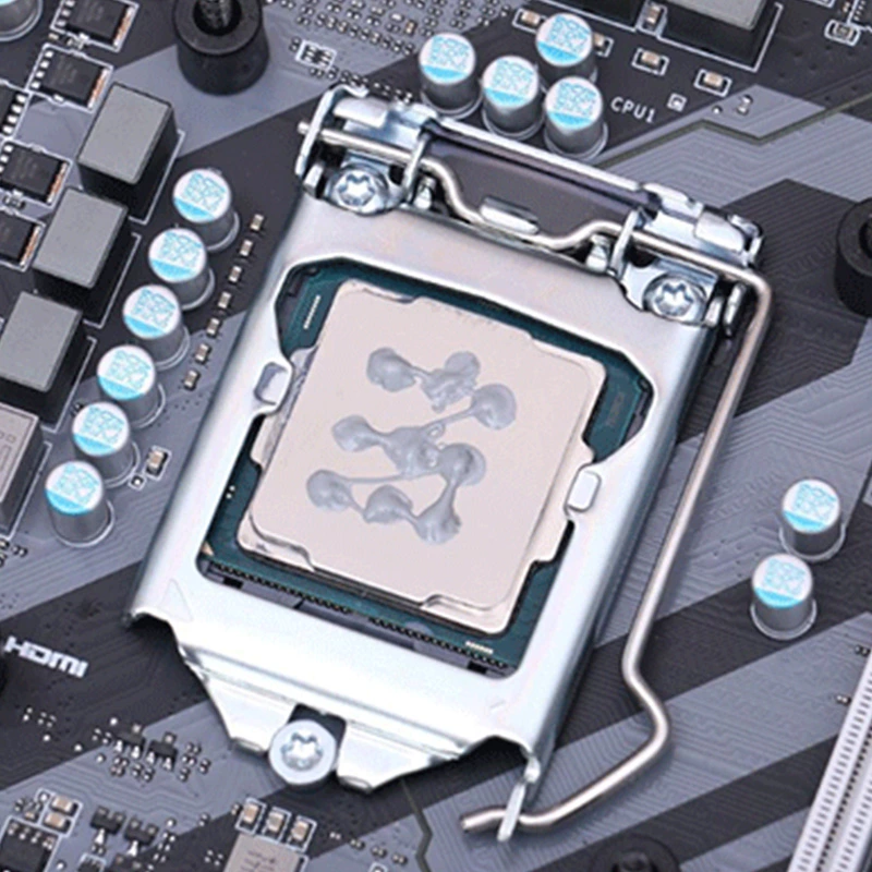
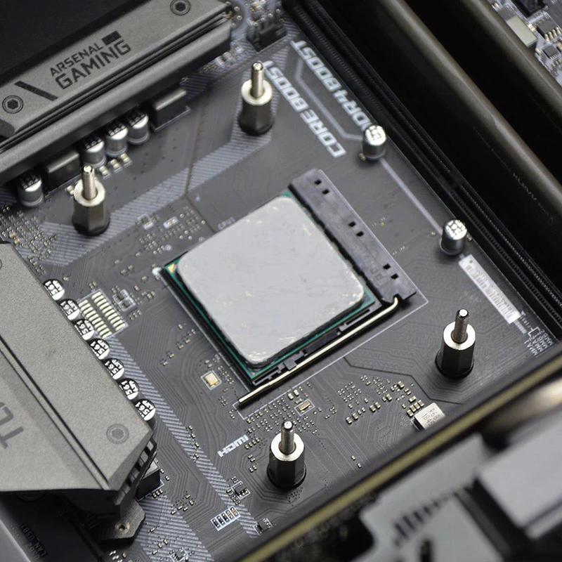
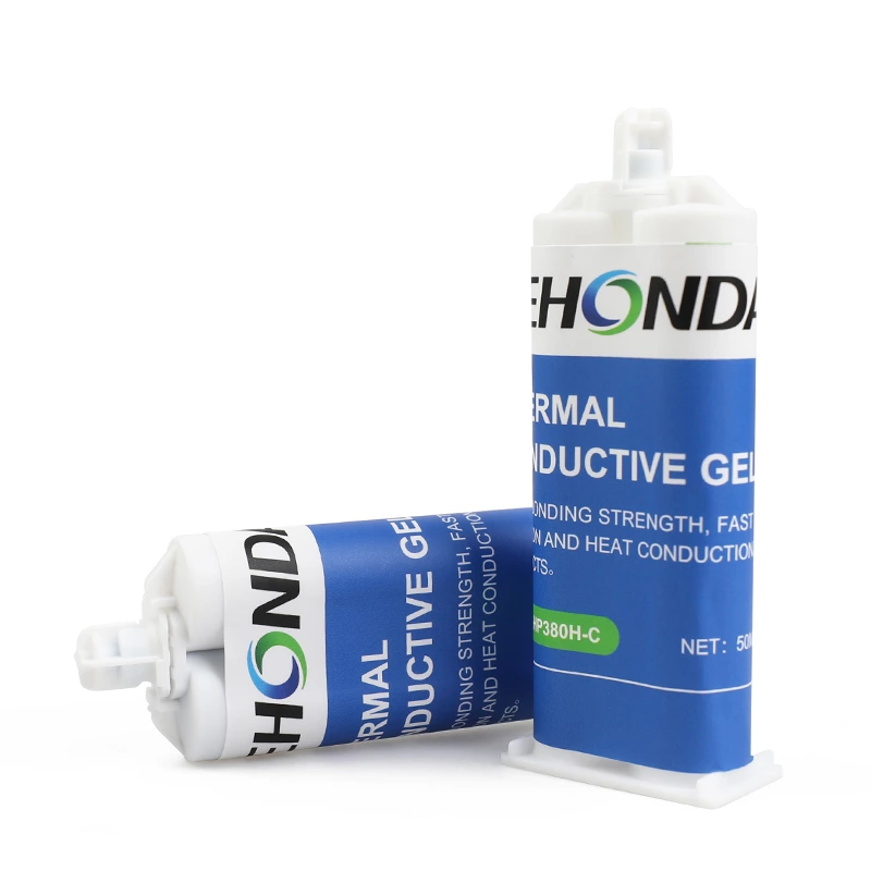
In the high-power frequency converter, the electric energy conversion is very large, even if the efficiency loss is low, it will cause the generation of thousands of watts of waste heat, so we must try to dissipate the heat. The heat of the inverter mainly comes from the IGBT. The heat of the IGBT is concentrated at the moment of on and off, so when the switching frequency is high, the heat generated by the inverter will also increase. FEHONDA Thermally grease can quickly fill the micropores at the interface due to its excellent wettability.Greatly reduce the interface thermal resistance and quickly dissipate the heat of the IGBT. Thereby prolonging the service life of the frequency converter and improving its reliability.Silicone grease can be applied by spot brushing, brushing,
screen printing, etc., which is easy to apply.
Inverter Solutions
FEHONDA | Thermal Materials Technical Article
Thermal Materials for Industrial Inverters
The IGBT loses its life one thermal cycle at a time — and the interface layer decides how fast
1.Two field failures that trace back to the interface
Pump-out
As the drive cycles between loaded and idle, the baseplate and the heatsink expand and contract by slightly different amounts. That breathing action works material outward from the centre, over hundreds of thousands of cycles. The result is thinning where the heat actually is, voids filled with air instead of compound, and a hot spot directly over the emptiest part of the joint.
This is a well-recognised failure mode in industrial drives, and it is one of the two reasons to consider a format other than grease in high-cycling applications.
Unit-to-unit spread
The second is a manufacturing problem rather than an ageing one, and it is frequently misdiagnosed. If thermal compound is applied by hand, the amount varies between operators and shifts, and bond line thickness varies with it. Published production analysis attributes junction temperature spreads of 8 to 15 °C across a single batch to inconsistent application alone — with units that are otherwise electrically identical.
The fix is a controlled format. A pad has its thickness controlled by the manufacturer, which narrows the distribution immediately. Or, if grease is retained for a technical reason, move to calibrated dispensing with in-process volume verification rather than a bead from a tube.
2.Application methods
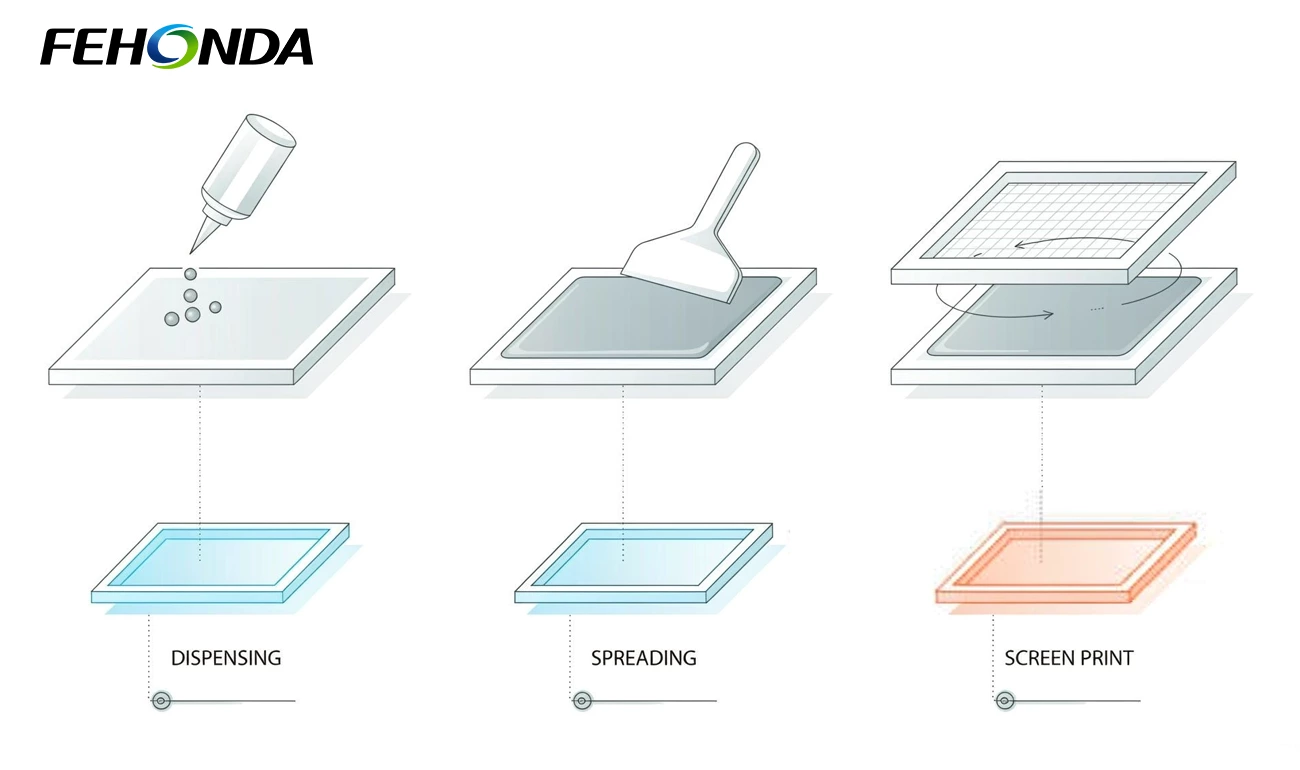
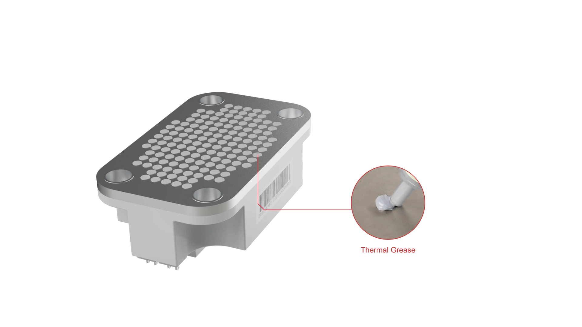
Figure 2. Three application methods: dispensing, spreading and screen printing.
FEHONDA thermal grease is formulated for all three of the methods used in drive production, and the choice between them is mostly about volume and repeatability rather than about the material.
| Method | How it works | Where it fits |
| Spot dispensing | Measured deposit applied by syringe or cartridge | Low volume, service and repair, and any position where the shape is irregular |
| Brushing or spreading | Material spread with a spatula or blade to an even thin film | Low volume assembly and rework; needs a trained hand to stay consistent |
| Screen printing | Material drawn across a mesh stencil onto the surface | Volume production — the most repeatable way to control deposit thickness across a batch |
Whichever method is used, two checks are worth building into the process: verify the applied film at several points across the surface before mating, and torque the fasteners in a cross pattern to a calibrated value so the layer seats evenly rather than tilting the module.
3. FEHONDA materials for industrial inverters
FEHONDA supplies thermal grease, pads, gels, phase change materials, potting compounds and conformal coatings for power conversion equipment, with thermal conductivity grades spanning 1.5 to 6.0 W/(m·K). The table maps the range to inverter positions.
| Product | Conductivity | Where it goes in an inverter | Why it is chosen there |
| Thermal grease | 1.5–6.0 W/(m·K) | IGBT module baseplate to heatsink | Excellent wettability fills the micro-voids in the machined surfaces and drives interface resistance down. Applies by dispensing, brushing or screen printing, so it fits low-volume and volume production alike. This is the classic IGBT interface material |
| Thermal pad | 1.5–6.0 W/(m·K) | Where a controlled, repeatable bond line matters more than absolute minimum resistance | Factory-controlled thickness removes operator variation, and the solid format removes pump-out risk. The usual answer where production spread or high cycling is the problem |
| Thermally conductive gel | 1.5–6.0 W/(m·K) | Variable gaps and mixed-height components on the power and control boards | Dispensable and low stress, so it fills geometry a pre-cut pad cannot, and suits automated production |
| Phase change material | Typically around 8.5 W/(m·K) | Power devices where a stable long-term interface is wanted | Solid at room temperature for clean handling, then flows at its transition temperature to wet the surfaces fully. A common choice where pump-out has been the historic failure |
| Thermally conductive silica (RTV adhesive) | 1.5–3.0 W/(m·K) | Bonding components to the housing or an internal spreader | Combines a heat path with mechanical retention, useful where cabinet vibration would otherwise work a joint loose |
The selection principle is unchanged from other power electronics: conductivity sets the ceiling, but wetting and bond line thickness set the result. A material that wets both surfaces fully at a thin, even bond line will beat a nominally better one applied thickly every time.
4. Why choose FEHONDA
- Wettability that fills the interface. Our thermal grease is formulated to flow into the micro-voids of machined and extruded surfaces, which is what actually reduces interface thermal resistance. On an IGBT baseplate, that is the property that matters.
- A format for every production reality. Grease for minimum resistance, pads where repeatability and pump-out resistance matter, gels for automated dispensing, and phase change material where the interface has to stay put. We will recommend the format that fits your cycling profile and build volume, not the one with the biggest number.
- Grades matched to the position. From 1.5 to 6.0 W/(m·K), covering the IGBT interface, the diode and rectifier positions, the power board and the control board. We will not oversell a top grade for a position where a thinner bond line would do more.
- Application support that reaches the line. Guidance on screen printing parameters, dispensing volume control, bond line verification and torque sequence — because on a power module the process is most of the result.
- Documentation for a real review. Thermal conductivity with test method and bond line thickness, thermal resistance at stated pressure, continuous operating temperature range, dielectric strength where isolation is needed, and RoHS and REACH declarations with supporting test reports.
- Customisation. Viscosity matched to your printing or dispensing process, pack sizes from service tubes to bulk, private-label and OEM packaging. Send us the module footprint, your flatness and roughness figures, and your cycling profile, and we will return a shortlist rather than a catalogue.
5. Working with FEHONDA
FEHONDA supplies thermal grease, pads, gels, phase change materials, potting compounds, conformal coatings and thermal silica for industrial inverters and variable frequency drives, with thermal conductivity grades spanning 1.5 to 6.0 W/(m·K).
Our sales and engineering support teams help with material and format selection against your module footprint and duty cycle, printing and dispensing trials, bond line verification, compliance documentation, custom viscosity and pack sizes, and OEM packaging. Send us the module drawing, your surface flatness and roughness, your switching frequency and cycling profile, and your production volume, and we will return a shortlist, sample recommendations and lead time. Please submit your request via our custom service form to ensure a faster response.
6. Frequently asked questions
Why does an inverter produce so much heat?
Because it handles a lot of power, and because IGBT losses concentrate into the switching transitions rather than spreading evenly. Even a highly efficient large drive rejects kilowatts. A 500 kW drive at 98 percent efficiency still has around 10 kW to remove.
Does switching frequency affect cooling requirements?
Yes, directly. Conduction loss is roughly independent of switching frequency, but switching loss scales with it. Raising the carrier frequency reduces motor noise and smooths the current waveform, and the drive pays for it in heat at the same load.
What junction temperature should I design to?
Datasheet limits are commonly 150 °C or 175 °C, but designing to the limit costs service life. Mean junction temperature and the size of the temperature swing both drive fatigue in bond wires and solder layers, so the target should be a comfortable margin below the limit rather than the limit itself.
How thick should the thermal compound layer be?
Thin and even. The usual target for flat power module mounting is 50 to 100 µm. Too thin leaves air voids, which are far worse than compound; too thick inserts a deliberate barrier, because even a good compound conducts far less than the copper and aluminium either side of it.
What is pump-out?
The gradual migration of thermal compound out of the joint under repeated thermal cycling. Expansion mismatch between baseplate and heatsink works material outward from the centre, leaving voids and a hot spot over the emptiest area. It is a recognised failure mode in industrial drives, and a pad or phase change material is the usual answer.
Should I use grease or a pad?
Grease where minimum interface resistance is the priority and the application process is controlled. A pad where production repeatability matters — manufacturer-controlled thickness removes the operator variation that produces 8 to 15 °C junction temperature spread across a batch — or where cycling severity makes pump-out a real risk.
How should thermal grease be applied?
By dispensing, brushing or screen printing depending on volume. For production, screen printing gives the most repeatable deposit. Verify film thickness at several points before mating, and torque fasteners in a cross pattern to a calibrated value so the layer seats evenly.
What should I ask a material supplier for?
Thermal resistance at your real bond line and mounting pressure, not just a conductivity figure; continuous operating temperature range; dielectric strength where the interface is also a barrier; and pump-out and thermal cycling data if the duty cycle is severe. For European programmes add RoHS and REACH declarations with supporting test reports.