B. The Advantage of Putty: When to Choose it Over Traditional Thermal Pads
Compared to traditional thermal pads, thermal putty offers significant advantages in various application scenarios. Its core strength lies in its superior conformability, allowing it to perfectly adapt to uneven component surfaces, varying component heights, and complex geometries where pre-cut pads might fail to achieve optimal contact. This means that in applications with non-uniform component heights or irregular surfaces, thermal putty can achieve more comprehensive contact, thereby enhancing cooling efficiency.
Thermal putty effectively fills a wide range of gap thicknesses, typically from 0.2mm up to 3.0mm or more, eliminating the need for users to stock multiple pad SKUs. Furthermore, some high-quality thermal putties, such as select products from Fehonda, provide excellent thermal conductivity while their soft texture exerts less mechanical stress on delicate components, which is particularly important for protecting sensitive electronics.
Consequently, thermal putty is especially suitable for Video RAM (VRAM) and Voltage Regulator Modules (VRMs) on Graphics Processing Units (GPUs), components within laptops where space is constrained and component heights vary, gaming consoles (like PlayStation, Xbox), and other electronic devices requiring effective filling of irregular gaps.
In modern electronic devices, especially compact ones like laptops and high-performance GPUs, the auxiliary components surrounding the main die (e.g., VRAM, power stages) often have varying heights, and precise gap data is not always available. This makes the selection of traditional thermal pad thickness a significant challenge: if a pad is too thin, it won't make contact, creating an air gap; if it's too thick, it can prevent the heatsink from properly seating on the primary die, compromising core cooling. Thermal putty, with its excellent flowability and plasticity, elegantly solves this issue by conforming to the actual gap present, ensuring tight contact with all components without requiring users to guess or measure numerous tiny gaps. This not only simplifies the DIY repair and upgrade process but also often leads to more reliable thermal performance. Thus, when dealing with such irregular or unknown gaps, thermal putty is often considered a smarter, more modern solution.
Table 1: Thermal Putty vs. Traditional Thermal Pads – A Comparative Overview
| Feature |
Thermal Putty |
Traditional Thermal Pads |
| Conformability to Irregular Surfaces |
Excellent, flowable to fill voids |
Limited, relies on its own elasticity |
| Gap Filling Range |
Wider, typically adaptable to various thicknesses (e.g., 0.2mm-3.0mm+) |
Fixed thickness, requires precise selection |
| Initial Application Ease |
Requires some skill to control amount and spread |
Simple, pre-cut, direct application |
| Reusability |
Some high-quality products can be reused if clean |
Generally not recommended for reuse, prone to damage/degradation |
| Risk of Incorrect Thickness Selection |
Lower, self-adapts to gaps |
Higher, too thick or too thin impacts cooling |
| Typical Application Components |
GPU VRAM/VRMs, laptop internal components, gaming consoles, irregular surface components, etc. |
CPU/GPU (in some cases), SSDs, RAM modules, other flat surface components, etc. |
II. Getting Started: Essential Preparations for Thermal Putty Application
A. Gathering Your Toolkit
Successful application of thermal putty requires a proper set of tools. Here's a recommended list:
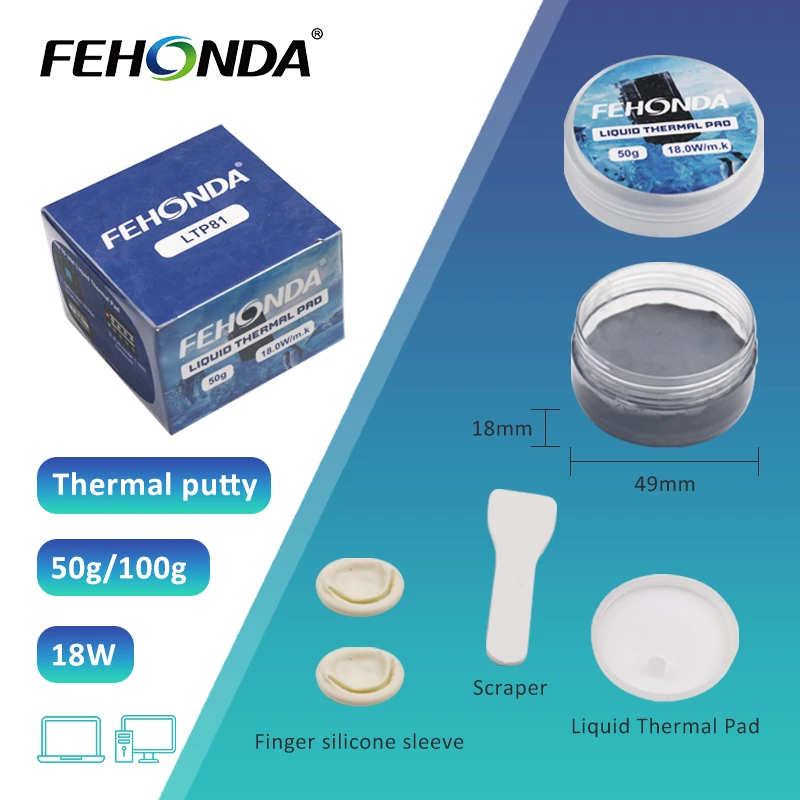
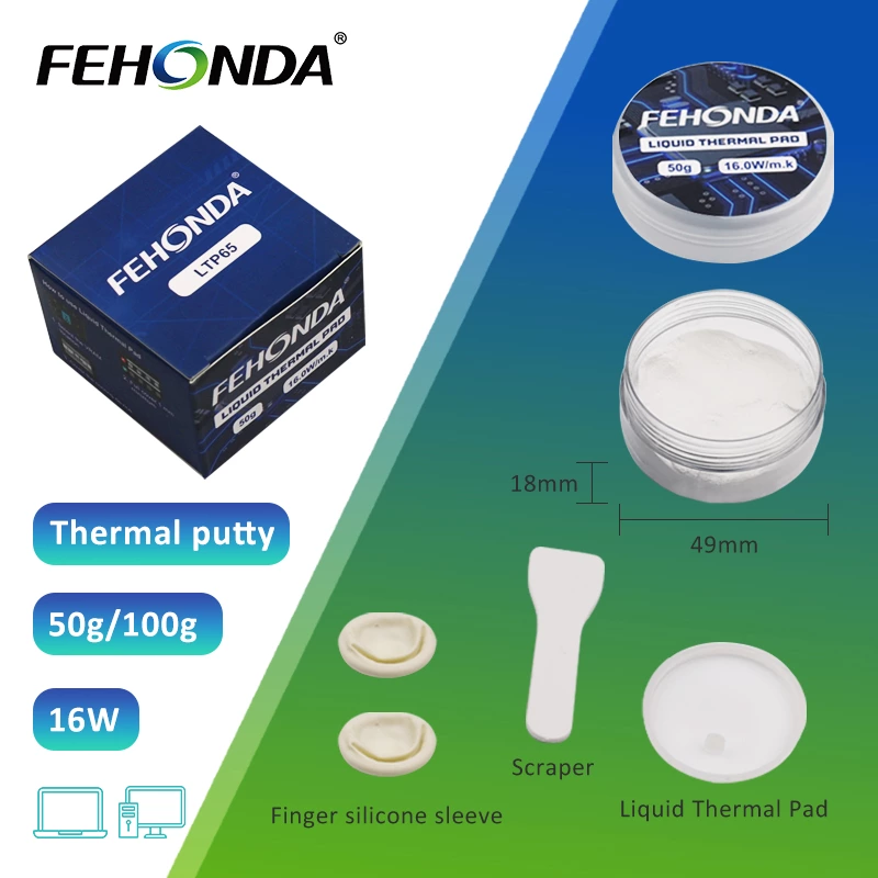
- High-quality thermal putty: For instance, Fehonda LTP81 (18W/mK thermal conductivity) or LTP65 (16W/mK thermal conductivity). Opting for such non-conductive products significantly enhances operational safety.
- Isopropyl alcohol (IPA): 90%+ concentration, for cleaning component surfaces.
- Lint-free cloths or swabs: Microfiber cloths are preferred for wiping. Coffee filters are also a lint-free alternative.
- Non-metallic spatula or spreader: Often included with thermal putty products like Fehonda LTP65.
- Nitrile gloves: Recommended when manually applying or shaping putty to maintain cleanliness and avoid direct skin contact.
- Anti-static wrist strap: Standard safety practice for any PC hardware manipulation.
- Screwdrivers appropriate for your device.
B. Safety First: Protecting Yourself and Your Components
- Complete Power Down: Ensure the device is fully powered off and unplugged. For laptops, also disconnect the battery if possible.
- ESD Precautions: Electrostatic discharge can damage sensitive electronic components. Wear an anti-static wrist strap or touch a grounded metal object before starting work to discharge any static electricity from your body.
C. The Critical Cleaning Step: Removing Old Thermal Interface Material
Thoroughly cleaning the contact surfaces is paramount to ensure the new thermal putty performs optimally. Any residual old TIM, dust, or oils will impede heat transfer by acting as an insulating layer or creating an uneven surface.
- Removing Old Thermal Pads: Gently peel off old pads. If they are brittle or stuck, carefully lift an edge using a plastic spudger or your fingernail. Avoid using sharp metal tools that could scratch the PCB or components.
- Removing Old Thermal Paste/Putty Residue:
- Initial Wipe: Use a dry, lint-free cloth or a plastic scraper to remove the bulk of the old paste or putty.
- IPA Cleaning: Apply 90%+ IPA to a lint-free cloth or swab. Gently wipe the surfaces of the components (e.g., VRAM, VRMs) and the heatsink contact areas. You can wipe in one direction or use small circular motions until all residue is gone.
- Stubborn Residue Treatment: For very hardened paste, allowing IPA to soak on the surface for a moment can help dissolve it. Acetone can be a last resort for extremely stubborn residue on heatsinks (avoid direct application on PCBs if possible), but IPA is generally safer for components.
- Drying: Ensure all cleaned surfaces are completely dry before applying new putty. IPA evaporates quickly.
The thoroughness of the cleaning step directly impacts the final performance of the new thermal interface material. This is a stage that should not be rushed.
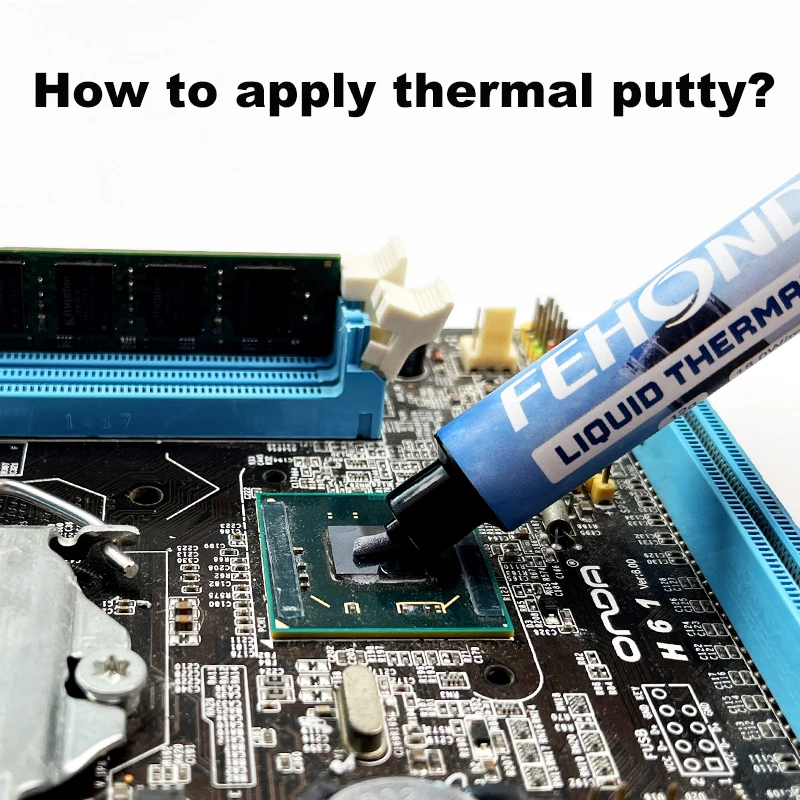
III. The Art of Application: A Step-by-Step Guide to Using Thermal Putty Effectively
A. Understanding the Goal: Optimal Contact and Complete Gap Filling
The primary objective when applying thermal putty is to completely fill all air voids between the component surface (e.g., VRAM chip) and the heatsink contact point. Air is a poor thermal conductor, and eliminating it by establishing a continuous thermal pathway is key to improving heat dissipation.
B. How Much is Just Right? Estimating Thermal Putty Amount
Precise control over the amount of thermal putty is crucial. The general principle is: start with less than you think you need; you can always add more if necessary. Applying too much is harder to correct and can lead to problems.
- Visual Cues: For individual VRAM or VRM chips, a small bead or a short "log" of putty slightly smaller than the chip's surface area is often a good starting point. The goal is for the putty to spread and cover the entire chip under the pressure of the heatsink, with minimal excess squeeze-out.
- Device Reference: Some devices, like laptops, PS5, and Xbox Series X, already use thermal putty from the factory. If visible during disassembly, this can provide a reference for the amount used.
- High-quality putties like Fehonda's LTP81/LTP65 are designed to fill gaps typically ranging from 0.3mm to 3.0mm, so the applied amount should correspond to the target fill thickness.
C. Application Techniques for VRAM, VRMs, and Other Components
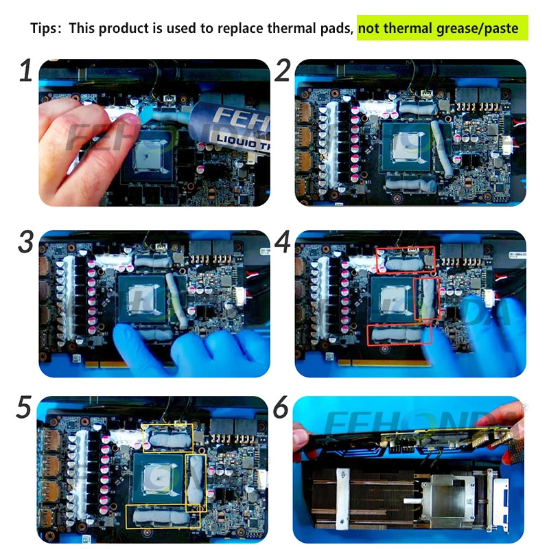
- Method 1: Shaping and Placing (Beads/Logs/Rolls – Most Common for VRAM/VRMs):
- Using gloved fingers or a clean spatula, take a small amount of putty.
- Roll it into a small bead, log, or thin strip appropriate for the size of the VRAM chip or VRM component.
- Place the shaped putty onto the center of each chip. The pressure from the heatsink will spread it.
- Visual Aid Description: A diagram should show small, appropriately sized putty shapes placed centrally on a row of VRAM chips.
- Method 2: Spatula Spreading (Less common for individual small chips, more for larger flat areas if putty is used there):
- Dispense a small amount of putty onto the component or a larger flat area.
- Use a non-metallic spatula to spread it into a thin, even layer.
- This method requires care to achieve uniform thickness and avoid air bubbles.
- Visual Aid Description: A diagram should show putty being spread thinly with a spatula on a larger, hypothetical flat component (less relevant for typical VRAM applications).
- Method 3: Dispensing via Syringe (For some putties, if packaged this way, or if user transfers to one):
- Some users transfer putty to smaller syringes for more precise dispensing of small amounts onto chips.
- This allows for controlled dots or lines.
D. The "Test Fit" or "Compression Check" Method (Crucial for Putty)
Since the final thickness of thermal putty is not pre-defined like thermal pads but is determined by the actual gap and the amount applied, checking the spread and contact is vital.
- Procedure:
- Apply putty to components as estimated.
- (Optional but recommended for a clean test fit: if concerned about putty sticking to the heatsink during the test, a very thin layer of plastic wrap can be placed over the putty ).
- Carefully place the heatsink onto the components, applying gentle, even pressure as you would for final assembly (or even partially secure it).
- Remove the heatsink and inspect the spread on both the components and the heatsink contact points.
- Look for:
- Complete coverage of the chip tops.
- Minimal squeeze-out (a little is okay; excessive means too much putty).
- Clear imprints on the heatsink, indicating good contact.
- Adjust putty amount if necessary (add more if coverage is incomplete, remove some if squeeze-out is excessive) and re-test or proceed to final assembly.
E. Reinstalling the Heatsink
- Alignment: Carefully align the heatsink over the components.
- Even Pressure: Apply gentle, even downward pressure. Avoid twisting or sliding the heatsink once it makes contact, as this can create air pockets or uneven spread.
- Screw Tightening: Tighten screws in a crisscross or diagonal pattern, a few turns at a time, to distribute pressure evenly. Do not overtighten.
For thermal putty application, the "test fit" is not optional but a core part of ensuring optimal results. This proactive step prevents many common issues.
IV. Best Practices & Avoiding Common Pitfalls
A. The "Too Much" vs. "Too Little" Dilemma
- Consequences of Too Little: Incomplete coverage, air gaps, poor heat transfer, hotspots.
- Consequences of Too Much: Excessive squeeze-out (messy, potential shorts if conductive – though quality putties like Fehonda's are non-conductive), and critically, can prevent the heatsink from making proper, firm contact with the main CPU/GPU die if putty on surrounding components is too thick, leading to higher core temperatures.
- Solution: Emphasize starting small and using the "test fit" method to adjust.
B. Ensuring Proper Die Contact (When Putty is Around CPU/GPU)
When thermal putty is used on auxiliary components like VRAM or VRMs that surround a CPU or GPU die, a critical yet easily overlooked issue can arise. If the putty on these surrounding components is too thick or an excessive amount is applied, it can physically "lift" the heatsink slightly. This reduces the mounting pressure and contact quality between the heatsink and the primary CPU/GPU die. Paradoxically, this can lead to worse core temperatures even if the VRAM/VRM temperatures improve. Therefore, it is crucial to use the "test fit" method to carefully inspect for a clear and even imprint of the CPU/GPU die on the heatsink. This indicates that the primary die is making good contact and that the putty on surrounding components is not interfering.
C. The Importance of Surface Cleanliness (Reiteration)
Reiterate that any contaminants will compromise performance; ensure contact surfaces are spotless.
D. When Not to Use Putty (Clarification)
Thermal putties like the Fehonda LTP series are primarily designed to replace thermal pads. They are generally not intended for direct application onto a CPU's Integrated Heat Spreader (IHS) or a GPU's die, where traditional thermal paste (grease) is used. The viscosity and gap-filling properties of such putties are optimized for larger, uneven gaps, not the ultra-thin bond lines required for direct die cooling.
E. A Note on Reusability: Can High-Quality Thermal Putty Be Reused?
- General Answer: High-quality, silicone-based thermal putty (like Fehonda products) can often be reshaped and reused if it remains clean, malleable, and has not dried out or undergone significant oil separation.
- Conditions for Reuse: Must be free of contaminants (dust, debris). If it has hardened or become crumbly, it should be replaced. Kneading might soften slightly dried putty.
- Fehonda's LTP series products are designed for durability and stability.
- Recommendation: While reusable in theory, for critical applications or if in doubt, a fresh application ensures the best performance. If reusing, ensure it's perfectly clean and still has its original consistency.
Table 2: Troubleshooting Common Thermal Putty Application Issues
| Issue |
Likely Cause(s) |
Solution(s) |
| High CPU/GPU die temps after application |
1. Putty on surrounding components is too thick, causing poor core contact. 2. Core thermal paste (if also replaced) improperly applied. |
1. Reduce putty amount on surrounding components; use "test fit" to ensure good core imprint. 2. Reapply core thermal paste correctly. |
| High VRAM/VRM temps after application |
1. Insufficient putty amount, incomplete coverage. 2. Poor contact between putty and heatsink. |
1. Increase putty amount to ensure full chip coverage. 2. Use "test fit" to check imprint; ensure heatsink is mounted flat and securely. |
| Putty squeezes out excessively |
Amount of putty applied is too large. |
Clean excess. Reduce amount for next application, adjust using "test fit." |
| No/poor imprint on heatsink after test fit |
1. Insufficient putty amount. 2. Heatsink not correctly installed or insufficient pressure. |
1. Increase putty amount. 2. Ensure heatsink is correctly aligned and screws are tightened evenly to appropriate pressure. |
V. Fehonda: Your Partner in Advanced Thermal Management
A. Commitment to Quality and Performance
Fehonda is dedicated to the research and development of high-performance, reliable TIMs, aiming to provide advanced thermal solutions for a wide range of electronic devices. Our thermal putty products, such as LTP81 (with a thermal conductivity of 18W/mK) and LTP65 (16W/mK), are formulated with high-quality raw materials. They feature non-conductive properties, excellent softness, conformability under low pressure, high-temperature resistance, and certifications (UL, RoHS, ISO), ensuring outstanding performance even in demanding application environments.
B. Where to Find Genuine Fehonda Products
To ensure you receive authentic, quality-guaranteed products, it is recommended to purchase Fehonda thermal solutions through official channels, such as the on AliExpress.
Integrating product mentions as examples of high-quality thermal putties naturally associates the brand with the expert advice provided. This approach focuses on the value products deliver, aligning with an expert, informative tone.
VI. Conclusion: Maintaining Optimal Performance with Proper Thermal Care
A. Recap of Benefits
Correctly applying high-quality thermal putty significantly improves the cooling of auxiliary heat-generating components such as VRAM and VRMs in electronic devices. This effectively lowers their operating temperatures, thereby enhancing overall system stability and contributing to the longevity of these critical parts.
B. Empowerment and Encouragement
We encourage users to be proactive in managing and maintaining their device's thermal health. With careful preparation and correct application techniques, every user can achieve professional-level thermal optimization, ensuring their devices operate at peak performance under various loads.
VII. Frequently Asked Questions (FAQ)
- Q1: How much thermal putty do I typically need for GPU VRAM or laptop VRMs?
- Answer: The amount depends on the chip size and quantity. Start with small beads or logs per chip and use the "test fit" method to confirm coverage. A 12g container of a quality thermal putty like Fehonda LTP81 or LTP65 is often sufficient for several components or a full GPU VRAM/VRM repaste.
- Q2: Is Fehonda thermal putty (e.g., LTP81, LTP65) electrically conductive?
- Answer: No, Fehonda LTP series putties are specifically designed to be electrically non-conductive, which is a significant safety advantage when working around sensitive electronic components.
- Q3: Can I reuse thermal putty if I remove the heatsink?
- Answer: Generally, high-quality silicone-based thermal putty like Fehonda's can be reused if it's clean, still malleable, and hasn't dried out. Carefully scrape it off, reshape, and reapply. If contaminated or hardened, replace it.
- Q4: What's the main difference between thermal putty and thermal paste (grease)?
- Answer: Thermal paste is for ultra-thin applications directly on CPU/GPU dies. Thermal putty is thicker, more conformable, and designed to replace thermal pads for filling larger, uneven gaps around components like VRAM/VRMs. Do not use them interchangeably unless the product specifically states it's for both.
- Q5: How do I clean thermal putty residue?
- Answer: Use 90%+ isopropyl alcohol and a lint-free cloth or swabs. Gently wipe until all residue is removed. Ensure the surface is dry before applying new TIM.
- Q6: Where can I buy Fehonda thermal putty?