Discover how avionics thermal pads conquer extreme temperatures, vibrations, and climate challenges. Learn key selection criteria: thermal conductivity (1–15 W/m·K), compression stress reduction, and compliance with MIL-STD-810. Optimize reliability for aircraft electronics

Thermal Pad Selection: Balancing Conductivity, Stress Tolerance & Application Scenarios
1. Typical environmental requirements for airborne electronic equipment
The application environment of airborne electronic equipment is relatively harsh, mainly reflected in the high and low temperature environment requirements, vibration requirements and climate protection requirements.
1.1 Temperature environment requirements
The high temperature of airborne electronic equipment generally requires an ambient temperature of 70 ℃, at which time the shell temperature of the components may reach 125 ℃. The low temperature requirement is -55 ℃, which requires the use temperature environment of the thermal pad to exceed the temperature range of -55 to 125 ℃. At the same time, the performance of the thermal pad as a polymer may decline if it works in a high or low temperature environment for a long time. Based on the high requirements of airborne electronic equipment for reliability and life, the performance of the thermal pad should be kept as stable as possible to avoid performance degradation due to long-term use.
1.2 Vibration environment requirements
Airborne electronic equipment needs to experience various vibration environments with the aircraft, including transportation, acceleration, impact, random vibration, falling, etc. The thermal pad must not fall off, delaminate, or have reduced thermal conductivity during the entire life cycle of the airborne electronic equipment.
1.3 Climate environment requirements
Airborne electronic equipment faces complex and harsh climate environment requirements, including salt spray, mold, humidity, sand and dust, rain, fluid pollution, etc. Although the thermal pad generally does not directly face these harsh environments, it should also have the corresponding ability to resist harsh climate environments to avoid failure after being indirectly affected.
2. Selection of thermal pads
The selection of thermal pads is mainly based on performance indicators. The performance of thermal pads is mainly divided into thermal performance, electrical performance, mechanical performance, and climate and environmental adaptability.
2.1 Thermal performance related indicators
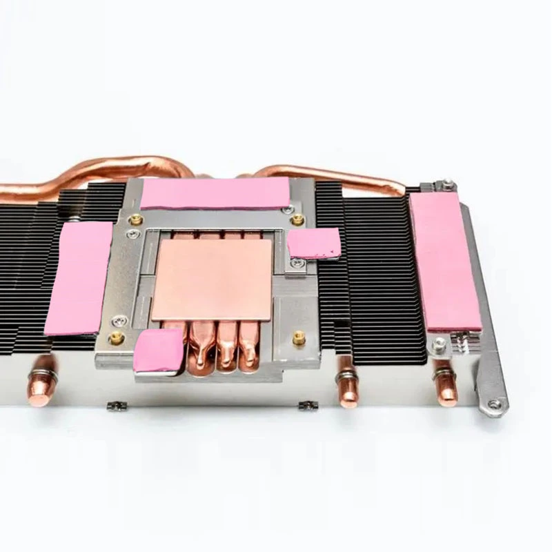
A typical thermal pad usage scenario is shown in Figure.
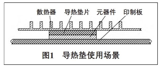
As can be seen from the figure, the heat generated by the components is transferred to the radiator through the thermal pad. According to the basic formula of heat flow transfer: Q=KAΔt/L, when the components are determined, Q (power consumption) and A (component area) are constants. Δt is inversely proportional to the thermal conductivity of the thermal pad and directly proportional to the thickness. Since the heat transfer interface suddenly expands and the heat flux density decays rapidly after the heat passes through the thermal pad, the thermal resistance of the thermal pad has a significant impact on heat dissipation. In principle, when selecting a thermal pad, you should try to choose a product with a high thermal conductivity and a thinner thickness.
In practical applications, it should be noted that the thermal resistance of thermal conductive materials is not completely proportional to the thickness. This is because most thermal conductive materials are not composed of a single component, and there will be nonlinear changes accordingly. As the thickness increases, the thermal resistance will definitely increase, and it is not necessarily a completely proportional linear relationship, but may be a steeper curve relationship, so the thickness has a greater impact on heat dissipation. However, since there are certain thickness specifications for thermal pads, the compression rate is generally not too large. When selecting the thickness of thermal pads, the welding error of components, the processing error of radiators, etc. should be comprehensively considered. It should be ensured that the deformation of the thermal pad can cover the error of the entire size chain. Therefore, when designing the thickness of the thermal pad, various factors should also be considered.
In terms of thermal conductivity, the thermal conductivity of products provided by mainstream thermal pad manufacturers is generally 5 W/(m·K) and 8 W/(m·K), and can reach up to 15 W/(m·K).
2.2 Electrical properties
Electrical properties mainly include breakdown voltage, electrical strength, volume resistivity, etc. Since the thermal pad is in direct contact with the structural parts and the radiator, which is generally made of metal, short circuit may occur if the component housing is metal packaged. Therefore, the thermal pad should have a certain insulation capacity. Considering that the common voltages of airborne electronic equipment include 270 V and 115 V, the thermal pad breakdown voltage is generally required to be above 5000 V and the electrical strength is above 10 kV/mm to ensure reliable insulation between the components and the radiator.
2.3 Mechanical properties
Mechanical properties include hardness, density, tear strength, compression set (normal temperature/high temperature/low temperature), compression rate, high temperature performance, low temperature performance, temperature change performance, flame retardant grade, etc. At present, the density of domestic thermal pads is between 2.5 and 3.5 g/cm3. Considering the consistent weight reduction demand of airborne electronic equipment, low-density thermal pads should be used as much as possible. The hardness index (shore 00) has a large range, and the Shore hardness is generally between 30 and 80. The hardness index is directly related to the pressure generated during the deformation of the thermal pad, so try to use products with lower hardness. Tear strength represents the strength of the material and its ability to resist damage during repeated disassembly. The general index is 0.4 to 0.6 kN/m. When selecting, products with higher strength should be considered as much as possible. Compression set represents the rebound ability of the thermal pad after compression. The test is conducted at 125, -55 and 23 ℃ respectively, with a compression rate of 25%, a compression time of 24 h, and 30 min after stress release. At present, the permanent deformation of domestic thermal pads under compression is between 40% and 65%, so it is not recommended to reuse thermal pads. The compression rate is generally measured after 20 psi pressure and 30 s, which represents the deformation capacity of the thermal pad. Generally, products with higher compression rates should be selected. High temperature performance refers to the thermal resistance of the thermal pad after 500 h/1000 h at 125 °C, low temperature performance refers to the thermal resistance after 500 h/1000 h at -55 °C, and temperature change performance refers to the thermal resistance after 500 h/1000 h from -55 to 125 °C, with a heating and cooling rate of 10 °C/min, and a stay time of 30 min at the extreme temperature. These three indicators represent the thermal pad's ability to resist high and low temperatures and temperature changes. Generally, products with smaller changes in indicators should be selected. At the same time, the thermal pad should meet the flame retardant grade requirements for materials in airborne equipment.
2.4 Climate and Environmental Adaptability
Climate and environmental adaptability includes salt spray, mold, damp heat, rain, fluid pollution, sand and dust, etc., which mainly prove that the product meets the use requirements of the entire life cycle. Since the thermal pad is generally installed inside the module and is not directly exposed to the climate environment, this performance can be tested with the whole machine. At the same time, it can also be completed separately according to the corresponding national military standards, such as salt spray 96 hours, damp heat 28 days or mold 10 days, and the thermal resistance test of the thermal pad performance is carried out after completion. The thermal conductivity of the thermal pad after the test is reduced to varying degrees, and the thermal pad with less performance change should be selected.
3. Research on the use of thermal pads
Before using thermal pads, they should first be cut into the same shape as the components so that after the thermal pads are attached to the components, the heat dissipation surface of the components can be fully utilized. In the process of using thermal pads, two issues related to use should be considered: one is the pressure generated by the thermal pads on the components during the compression process. The appropriate installation gap and compression rate design are important factors to ensure the long-term stable operation of the components. Another issue is that in order to fix the thermal pads and better fill the gaps, the thermal pads themselves have a certain viscosity. When the heat sink and components are separated after long-term use, a certain stress will be generated, which may cause cracks in the solder joints of the components and other faults.
3.1 Pressure
During the compression process of the thermal pad, a certain amount of pressure will be generated. At the same time, there are certain requirements for the pressure that components can withstand. Taking a CPU device as an example, the maximum allowable stress of the device specified in the component manual is 45 N. According to the area of the device, the maximum allowable pressure of the device is calculated to be 36.7 psi (253 kPa).
According to the thermal pad selection method, after determining the thermal pad model, its compression stress curve can be obtained from the manual. Taking the CHLT series thermal pad as an example, its compression stress curve is shown in the figure.
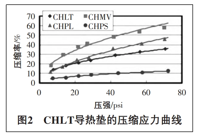
According to the maximum allowable pressure of the device of 36.7 psi, the compressive stress curve of the thermal pad is checked, and the maximum allowable compression rate of the thermal pad is 27%. Therefore, when designing the thickness of the thermal pad, the maximum compression rate cannot exceed 27%. At this time, if a thermal pad with a thickness of 1.5 mm is selected, the installation compression rate is selected as 20%, and the reserved gap of the thermal pad can be designed to be 1.2 mm. The 0.3 mm gap must meet the requirements of structural part size tolerance, component height tolerance, welding tolerance, etc., to ensure that the thermal pad can reliably contact the device without generating greater pressure. Among them, the height range of components in the device manual is generally larger, and the deformation of the thermal pad cannot meet this size. Therefore, it is necessary to measure components from different batches to determine the welding height error. In addition, the introduction of other variables (such as printed circuit board thickness, etc.) into the dimension chain should be avoided in structural design.

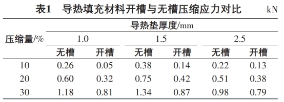
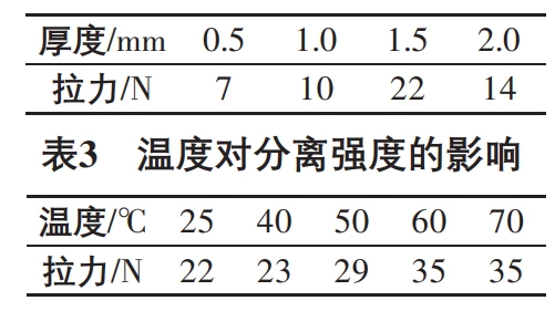
In order to reduce the compressive stress of the thermal pad, a slot can be made in the middle of the thermal pad. Generally speaking, when the area of the thermal pad is larger than 20 mm×20 mm, a slot can be designed in the center of the thermal pad. The recommended slot width is 1 mm, and the shape is determined according to the shape of the thermal pad. Table 1 shows the pressure comparison of different compression rates when a cross slot with a width of 1 mm×30 mm is made in the center of a certain type of 40 mm×40 mm thermal pad with different thicknesses.
It can be seen from the test that slotting the middle of the thermal conductive filling material can effectively reduce the stress caused by the compression of the thermal conductive filling material. Therefore, in the case where the components are more sensitive to pressure, the compressive stress can be reduced by slotting the thermal pad. The specific slot size and effect can be verified by testing.
3.2 Separation stress
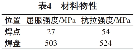
In order to ensure good contact and fixation between the thermal pad and the components or heat sink, the thermal pad itself has a certain viscosity. After long-term use, the components and the thermal pad, the heat sink and the thermal pad will be in close contact, and a certain stress will be generated during the disassembly process. Therefore, it is necessary to analyze and test the separation strength of the thermal pad during use to determine the impact on the components. Taking a certain type of thermal pad as an example, the thermal pad is made into a 30 mm × 30 mm sample. After compressing and deforming it by 20% and keeping it for 24 hours, a tensile gauge is used to test its separation force under different thickness conditions at room temperature, as shown in Table 2. The separation strength of a 1.5 mm thick thermal pad is tested under different temperature conditions.
From the test results, we can see that:
a. The separation strength of the thermal pad is related to the thickness, but not in direct proportion;
b. The increase in temperature will increase the separation strength of the thermal pad, which is not conducive to disassembly, so it is recommended to disassemble the thermal pad at room temperature.
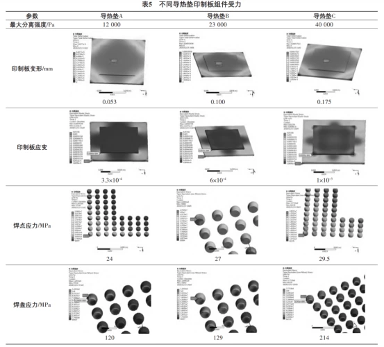
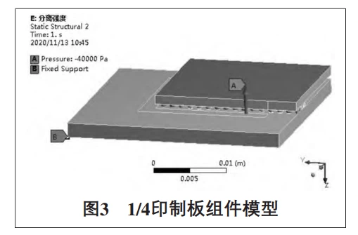
According to the tensile force obtained in the test, the influence on the components can be judged by finite element simulation. A standard printed circuit board assembly model is established (as shown in Figure 3). The size of the printed circuit board is 60 mm × 60 mm × 2 mm, the size of the component is 40 mm × 40 mm × 3 mm, the solder joint material is 63Sn37Pb, and the pad is copper. The four corners of the printed circuit board are constrained, and the separation force is applied to the top of the component to simulate the force of the printed circuit board assembly. Its material properties are shown in Table 4. Three different thermal pad separation forces are selected, and the simulation results are shown in Table 5.
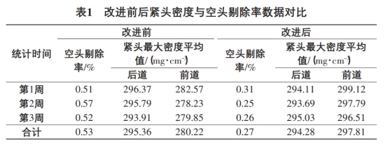
Taking the maximum PCB strain allowed by BGA devices as 6×10⁻⁴ as the qualified criterion, it can be found that the PCB strain and solder stress of thermal pad A are less than the criterion and meet the requirements. The PCB strain and solder stress of thermal pad B are equal to the criterion, with no safety margin. The PCB strain and solder stress of thermal pad C are greater than the criterion, with a risk of damage.
From the simulation results, it can be seen that if the separation force of the thermal pad is too large, there is indeed a risk of damage to the components, which should be considered during design. Therefore, when selecting a thermal pad, first consider choosing a thermal pad with adhesive on one side, which can effectively reduce the separation stress. Secondly, evaluate the viscosity of the thermal pad and select products with lower viscosity through testing and simulation during design.
Conclusion:
1. Extreme Environmental Adaptability
Thermal pads must operate reliably in -55°C to 125°C extremes, withstand high-intensity vibrations (transportation/impact/random vibration), and resist harsh climatic conditions (salt spray/mold/humidity). Compliance with 96-hour salt spray and 28-day humidity tests (per military standards like MIL-STD-810)ensures long-term stability.
2. Critical Performance Metrics
Thermal Performance: Prioritize thermal conductivity (5–15 W/(m·K)) and optimize thickness design to balance nonlinear thermal resistance growth (e.g., 1.5mm pads compressed by 20% to cover 0.3mm tolerance)
Electrical Safety: Breakdown voltage ≥5000 V and dielectric strength ≥10 kV/mm are mandatory to prevent short circuits in high-voltage systems (e.g., 270V avionics)
Mechanical Durability:
- Low hardness (Shore 00: 30–80) minimizes pressure on components.
- High tear strength (0.4–0.6 kN/m) ensures resistance to repeated disassembly.
- Low compression permanent deformation (<40%) guarantees stable contact under vibration
3. Application Optimization Strategies
Pressure Control: Slotting designs (e.g., 1mm-wide slots in 40×40mm pads) reduce compression stress by 30–50%, preventing overload on sensitive components like CPUs (max. pressure ≤36.7 psi)
Separation Stress Management: Use single-sided adhesive pads with peel strength <12,000 Pa to avoid solder joint damage during disassembly
Simulation Validation: Finite element analysis (FEA) quantifies strain on BGA components (threshold: 6×10⁻⁴) and validates separation force impacts