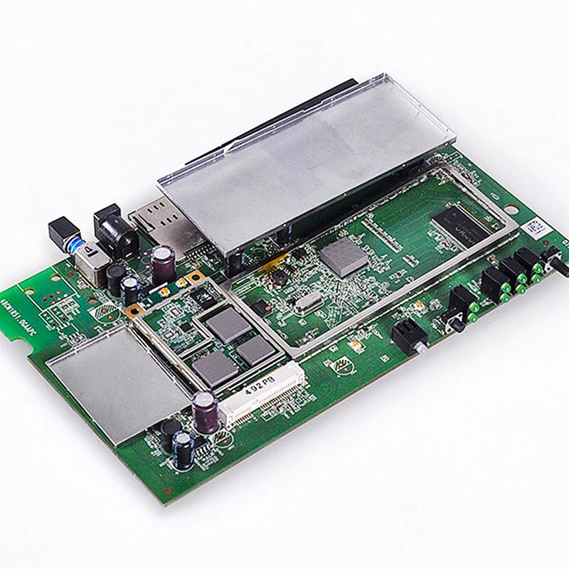
Power adapters are no strangers in our life. Use for a long time if the temperature is too high, it will seriously affect its working performance. Therefore, it is very important to use thermally
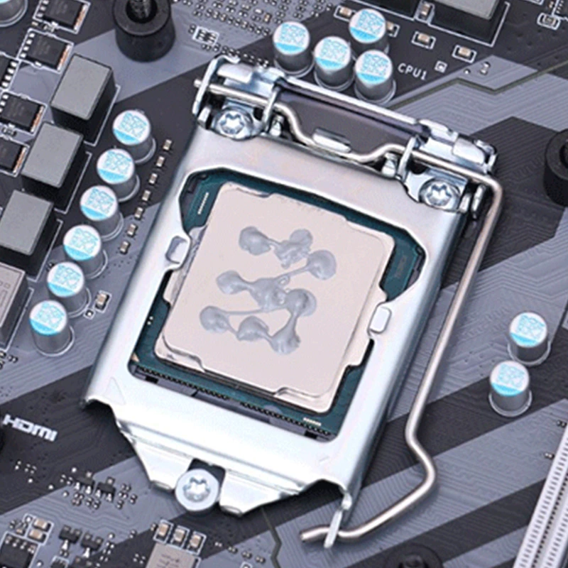
conductive materials reasonably. For electronic components, we can use FEHONDA thermal conductive silicone for thermal bonding and fixing. If there is a need for outdoor use, heat-conducting potting
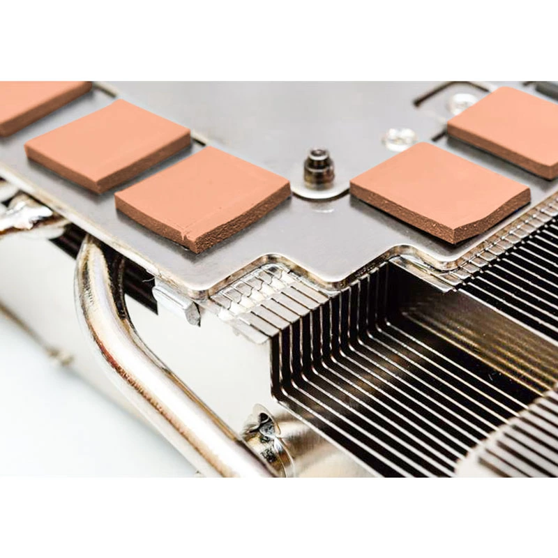
glue can also be used for partial or overall potting. On the back of the PCB board, we can add a thermally conductive pad or a thermally conductive silicone. This will help to fill the gaps and
dissipate heat in an eficient manner.
FEHONDA helps products operate efficiently and with long-term stability to ensure proper operation of your device.
Power Adapter Solutions
FEHONDA | Thermal Materials Selection Guide
Thermal Materials for Power Adapters
A four-step selection flow for sealed adapters and chargers
Most adapter thermal problems are solved backwards. The material is chosen first, from a conductivity table, and the symptom is dealt with afterwards if it appears at all.
This guide runs the other way: identify what is actually failing, then pick the material that addresses it.The reason that matters is the enclosure. An adapter sits in a sealed plastic box with no fan and no vents, so every watt of loss has to leave by conduction through the shell. In that geometry the interface is the bottleneck, and the interface is exactly what a conductivity table does not describe.
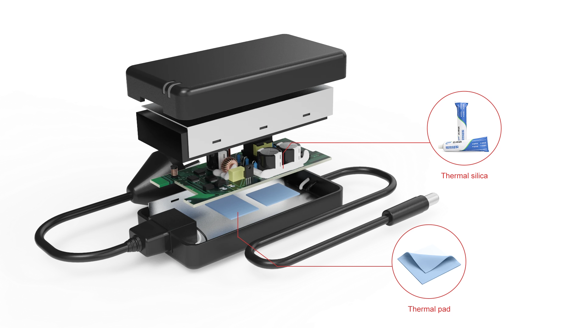
we can use FEHONDA thermal conductive silicone for thermal bonding and fixing. On the back of the PCB board, we can add a thermally conductive pad or a thermally conductive silicone to fill the gaps and help to dissipate the heat.
Step 1: Know your ceiling before you choose anything
Two numbers bound the whole design, and it is worth fixing them first because they decide how much help you actually need.
| Bound | Typical figure | Why it constrains the material choice |
| Heat to reject | Roughly 4 W on a 65 W adapter at 94 percent efficiency; legacy designs at 75 to 85 percent reject far more | Sets how much has to cross the interface |
| Case temperature ceiling | Rise typically held to about 30 to 35 °C over ambient, putting worst case around 70 to 75 °C | The practical limit is set by the nameplate label, which commonly degrades around 80 °C, not by the case material |
If your measured case temperature is already near that ceiling, the problem is the interface, and no material substitution at a component level will fix it.
Step 2: Match the symptom to the mechanism
Three failure signatures cover nearly everything an adapter thermal design gets blamed for. Each points at a different mechanism, and each has a different fix.
| Symptom | Likely mechanism | Confirm by | What it tells you |
| Units die after one to two years | Electrolytic capacitor dried out. Core temperature too high — including self-heating from ripple current through ESR, which can add 10 to 15 °C | Capacitor core temperature under load, not ambient | You need to lower internal temperature. Life roughly doubles for every 10 °C off the core |
| Full power for 20 to 60 minutes, then it drops | Thermal throttling. Protection engages around 90 °C case or 120 °C component and reduces output | Sustained-load run with logging | The GaN device is rarely the cause. The resistance around it is — air gaps and poor coupling to the case |
| Moisture or corrosion inside an outdoor unit | Negative-pressure pumping. The enclosure pushes air out when hot and draws humid air back in as it cools | Inspect a unit that has been through day-night cycling | A coating or partial fill is not enough. This needs a properly filled assembly |
Note that two of the three are not really about conductivity at all. One is about temperature, and one is about excluding air. That is why starting from a conductivity table tends to produce the wrong answer.
Step 3: Choose the material by situation
Once the mechanism is known, the material follows directly. FEHONDA supplies thermally conductive pads, gels, silica, potting compounds and conformal coatings across 1.5 to 6.0 W/(m·K).
| Your situation | Use | Recommended Thermal Conductivity | Why this and not the alternative |
| Component needs a heat path and mechanical retention together | Thermally conductive silica (RTV adhesive) | 1.5–3.0 W/(m·K) | One step does both bonding and conduction. A pad cannot retain a component, and a clip adds a part and an assembly step |
| Air gap between the PCB back side and the case | Thermal pad | 1.5–6.0 W/(m·K) | The most effective single addition on a sealed plastic adapter, because the shell is the only sink. Select thickness against your measured gap, not the datasheet |
| Mixed component heights, or automated dispensing | Thermally conductive gel | 1.5–6.0 W/(m·K) | Fills variable geometry without a fixed thickness. A pre-cut pad cannot bridge unequal heights |
| Cannot sustain rated output, or voids under components | Thermally conductive potting compound | 1.5–6.0 W/(m·K) | Replaces air with a conductive path from every surface to the case. Vacuum fill removes the micro-bubbles that create local hotspots |
| Outdoor installation or an IP67 requirement | Thermally conductive potting compound | 1.5–6.0 W/(m·K) | This is how the rating is achieved. Displaces air so moisture cannot condense, and anchors heavy parts against vibration |
One caution that applies to every row: contact beats conductivity in a sealed plastic box. A softer material that actually bridges the gap at your available assembly pressure will outperform a stiffer, higher-conductivity one that only partly contacts. Measure the gap first, then select.
Step 4: If potting, choose the chemistry for the installation
| Installation | Chemistry | Reason |
| Large day-to-night temperature swing, or a stack with very different expansion rates | Silicone | Stays elastic at low temperature and absorbs the stress between case, PCB and ferrite cores |
| Maximum thermal conductivity and structural rigidity wanted | Epoxy | Higher conductivity and a rigid, fully supported assembly |
Why FEHONDA
- We ask what failed before recommending a grade. Capacitor life, throttling and moisture ingress have different fixes, and a conductivity table cannot tell them apart.
- Both potting chemistries, selected for the installation rather than for the datasheet headline.
- Grades from 1.5 to 15.0 W/(m·K), matched to your measured gap and assembly force.
- Dispensing and vacuum potting support for volume production, with consistent deposit volume and clean cut-off.
- Custom die-cutting, thickness, colour coding, pack sizes and OEM packaging. Send us the enclosure drawing and gap range and we will return a shortlist, samples and lead time. Please submit your request via our custom service form to ensure a faster response.
Frequently asked questions
Why does an adapter get hot?
Because AC to DC conversion is lossy, and the losses leave as heat that has to cross a sealed plastic shell by conduction. Legacy designs run around 75 to 85 percent efficient; modern GaN designs reach the low to mid nineties, so a 65 W adapter at 94 percent still rejects roughly 4 W.
What is the weak point inside an adapter?
Usually the aluminium electrolytic capacitor, which is the only common board component with a life quoted in hours. Its life roughly doubles for every 10 °C off its core temperature — and core temperature includes self-heating from ripple current through ESR, not just the air around it.
Should I pot an indoor adapter?
Only if it is throttling or you need the sealing. Potting lets a compact design hold rated output instead of dropping it, at the cost of process complexity, weight and field repairability. If the unit is not throttling, a pad on the PCB back side is usually the better first move.
Epoxy or silicone potting?
Silicone where the temperature swing is large, because it stays elastic and absorbs the stress from differing expansion rates. Epoxy where maximum conductivity and rigidity are wanted. The installation decides it.