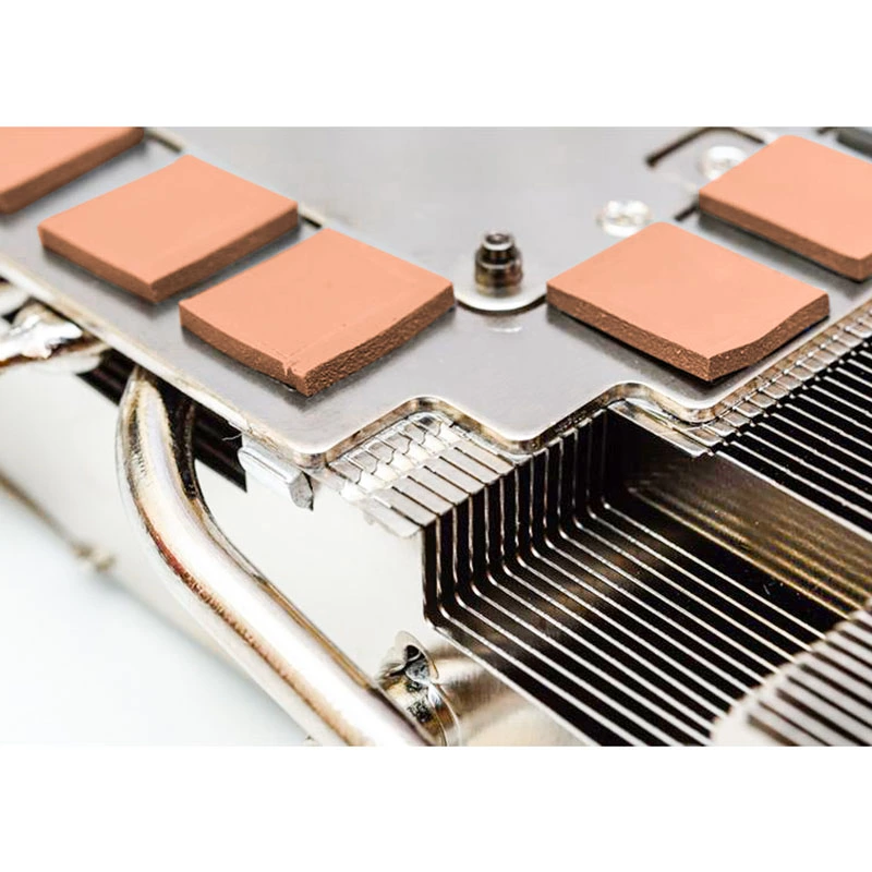
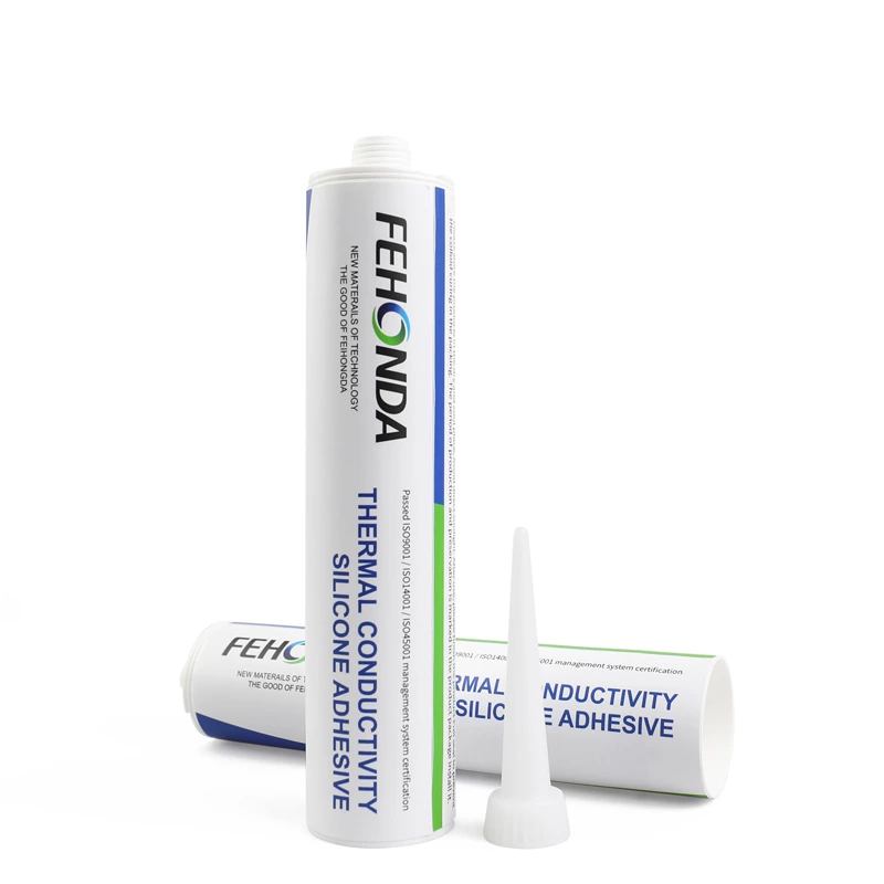
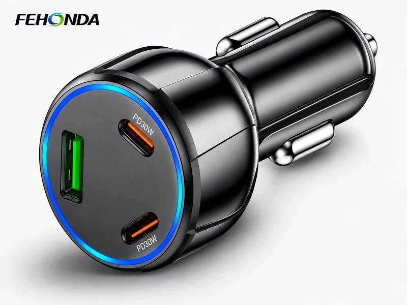
A 100 W car charger derates when a few watts of conversion loss cannot leave a thumb-sized shell in a sun-soaked cabin. This guide maps FEHONDA pads, gels, RTV silicones, absorbers and composite TIMs to eight positions across plug-in, wireless and console chargers — and marks the ones that need no material at all. Samples, small batches and die-cutting to your drawing.
In-Car Charger Thermal Solutions
FEHONDA | In-Car Charger Thermal Solutions
Thermal Materials for In-Car Chargers
A hundred watts in a cylinder the size of a thumb, in a car that has been sitting in the sun.
The phone shows fast charging when it is plugged in. Two minutes later the icon changes and the rate drops, although neither the charger, the cable nor the phone has failed. The controller has simply pulled back the output because something inside a small cylinder reached its temperature limit. In a product sold on a wattage number, that derating is the whole complaint.
An in-car charger is a DC-DC converter running from the 12 V socket and delivering USB Power Delivery profiles from 5 V up to 20 V. Published designs now cover roughly 65 to 160 W at 92 to 97 percent conversion efficiency. At 100 W and 95 percent, around five watts of heat has to leave a housing barely larger than a thumb — a far higher heat flux than a set-top box spreads across a whole board. The only heat sink available is the outer shell, and industry-reported measurements place windscreen-adjacent surfaces in a parked car at 70 to 90 °C. The material decision is therefore made before the enclosure tooling is cut.
What makes the small cylinder difficult
Figure 1. Solar load, the conversion loss concentrated at the switching devices, and the only available heat path: outward into the shell.
Three constraints arrive together. The first is heat flux. Published teardowns of high-power car chargers show the switching devices coupled to the aluminium shell through a pad in the region of 4 W/(m·K), with shell temperatures in the high sixties under full load. The interface is short, but it carries everything: any unfilled void is air, and air is an insulator. Lowering the switching frequency can cut converter temperature substantially, but that is a circuit decision and it moves heat into the inductor rather than removing it.
The second is the 12 V supply itself. It is not a clean rail. Cold crank can drop it below 5 V for tens of milliseconds, and an unsuppressed load dump per ISO 7637-2 pulse 5a can push a transient towards 87 V for up to 400 ms. Conducted emissions are assessed against CISPR 25, and the switching converter is one of the sources. A carbon-filled or otherwise conductive interface placed near a live node must therefore be treated as an electrical part, not just a thermal one; where a joint also has to isolate, confirm dielectric strength at the thickness used.
The third is mechanical. A plug-in charger is held by springs in a socket whose depth and contact balance vary between vehicles. Contact resistance rises as the joint warms, so a marginal connection that is fine when cold can drift into a slow thermal climb mid-drive. Road vibration works the same joint over thousands of hours. That is why a material which only conducts heat, but can be pumped out or shift position, is the wrong specification here.
Three shapes, three bills
The phrase in-car charger covers three different assemblies, and they do not share a material list. The plug-in PD charger is a sealed cylinder or a short metal barrel with one to three ports. A wireless charging mount is a flat transmit coil with a magnetic absorber sheet behind it, holding a phone against the dashboard. A centre-console module is a shallow metal box built into the vehicle, with two or more ports, a wiring harness and a lid. The first has almost no internal volume, the second has to keep heat away from a lithium cell it does not control, and the third has a lid that can serve as a broad heat spreader.
FEHONDA supplies thermal pads, gels, silicone rubber, RTV sealants, potting compounds, wave absorbers, composite TIM constructions and conformal coatings from 1.5 to 6.0 W/(m·K). The table assigns them to positions across all three shapes.
| Position | FEHONDA material | Why this position |
| Switching MOSFET / GaN devices to outer shell | Thermal pad, 2.0 to 4.5 W/(m·K); ultra-soft 2 to 3 W/(m·K), Shore 00 25 to 35 where clamping force is low | The main conduction path out of a sealed cylinder. A controlled bond line beats a higher conductivity figure with an air gap |
| Inductor and irregular power components | Thermally conductive RTV silicone, 1 to 2 W/(m·K) | Gives a heat path and mechanical retention in one step. A cut pad cannot sit on a wound magnetic part, and vibration will move it |
| Uneven heights under a shield or around the USB ports | Thermal gel, 1 to 3.5 W/(m·K), Shore 00 40 to 75 | Fills the gap that is actually there at low assembly pressure and suits automated dispensing |
| Where the interface is also a voltage barrier | Composite TIM with a reinforced insulating layer | The soft layer provides contact, the reinforcement provides dielectric strength and resistance to puncture. A conductive filler cannot serve as this barrier |
| PCB, board level | UV or RTV conformal coating | Protection against condensation and humidity in a cabin that cycles daily. It does not fill gaps and is not a thermal interface |
| Wireless charging coil, behind the transmit winding | Wave-absorbing material, selected for the 110 to 205 kHz band, with a conduction path to the bracket | Guides flux, shields the metal bracket and the phone from eddy currents, and reduces the loss that would otherwise become heat next to the battery |
| Console module, board to metal lid | Soft thermal pad or gel, 1.5 to 2.0 W/(m·K) | Broad contact into the lid is the cheapest available heat path in a shallow sealed box |
| Console module, lid seam | Flame-retardant RTV silicone sealant | Holds out moisture and dust through daily temperature cycling while remaining serviceable |
Figure 2. Material positions in a plug-in PD charger, a wireless charging mount and a console module.
The wireless row deserves one extra note. A Qi link at around 80 percent transfer efficiency turns several watts into heat, and the phone on the other side of the coil contains the lithium cell that heat will age. An absorber works by dielectric loss — it converts electromagnetic energy into heat inside the material. Suppressing the field but trapping that heat is moving the problem, not solving it, so the absorber needs its own route into the bracket. It should also be kept clear of NFC and antenna geometry, and verified with S-parameters rather than a spectrum reading alone.
What to leave off the bill
Three items appear on early drafts and usually do not survive. A full potting fill of a plug-in charger makes a sealed, non-repairable part, and a low-conductivity resin traps more heat than it removes; keep potting, if the design calls for it, to a separate power sub-assembly in the console module and specify a thermally conductive grade. Graphite film and carbon fibre pads at 25.0 or 35.0 W/(m·K) through-plane are built for concentrated hotspots with a validated conduction path; a small shell radiating into hot cabin air cannot reject enough heat to justify either. Low-volatility and low-oil grades are made for sealed optical cavities in cameras and optical modules, where siloxanes condense on a lens; a charger has no optical surface, so that premium buys nothing here.
Two failures are not material failures either. A socket that browns at the tip is a contact-geometry and spring-balance problem, and a non-certified cable that forces a lower PD profile is a cable problem. Both look like thermal derating from the driver's seat. Free measures come first as well: keep the charger out of the windscreen boundary layer, avoid a closed console bin, and make sure the metal shell actually seats against the socket.
Specifying and validating
Ask for thermal resistance at the bond line and assembly pressure actually used, not conductivity alone. Name the hardness scale explicitly — Shore 00 is not Shore A, and a figure without its scale is not a specification. Where the joint sits near a supply rail, request dielectric strength at a stated thickness and method, and the flame classification at the thickness you intend to buy. For the conformal coating, the automotive UV specification used across programmes is a useful template: insulation resistance after 40 °C / 93% RH for 24 to 168 hours, electrical performance after 85 °C / 85% RH for 1,000 hours, and post-ageing appearance and adhesion alongside cure time. Ask for retained values after ageing, not only as-new ones.
Then validate the assembly, not the coupon: full-load operation at the highest expected cabin temperature, thermal shock across the installed temperature range, vibration with the charger seated in a representative socket, and the supply-transient and conducted-emission work under ISO 7637-2 and CISPR 25. A charger that passes on a bench at 25 °C and later resets on a load dump has not failed a thermal test; it has skipped an electrical one. The two belong in the same report.
Why FEHONDA
One supplier covers the 1.5 to 6.0 W/(m·K) ladder in pads, gels, silicone rubber, RTV sealants, potting compounds, absorbers, composite TIM constructions and conformal coatings, so a family spanning plug-in chargers, wireless mounts and console modules does not need several vendor qualifications. Those layers sit against one another inside a very small volume: an RTV cure by-product, a pad liner release agent, an absorber adhesive or an uncured gel can migrate into the neighbouring layer and change its adhesion or insulation. Keeping them with one supplier makes that an engineering question rather than a question of responsibility.
Pads are die-cut to the drawing, with thickness matched to the measured gap, hardness selected on the Shore 00 scale, colour coding to separate grades on the line, single- or double-sided liners, and kitting by position. Samples turn around quickly, small-batch orders are accepted for pilot builds, and a revised drawing produces a revised sample rather than a new negotiation. Send the housing drawing, the gap and clamping force at each position, the output power and PD profiles, the mounting location and your production volume, and the response is a material map with samples and a lead time. RoHS and REACH declarations with supporting test reports are available on request. For a small or mid-sized team the practical difference is access: the people making the material are the ones answering the question about it.
Please submit your request via our custom service form to ensure a faster response.