FEHONDA | Thermal Materials Technical Article
1. What an on-board charger actually does
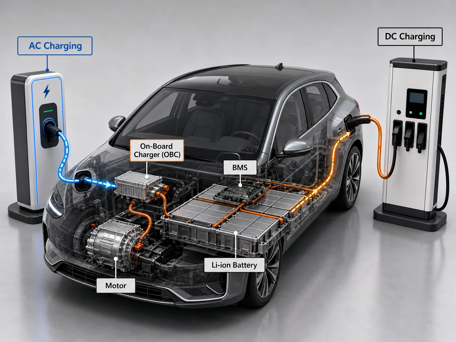
The OBC bridges the AC grid and DC battery pack through three functional blocks: input stage, control logic, and power conversion.
- Input: Single-phase 220 V AC (3.3–6.6 kW) or three-phase 380 V AC (11–22 kW).
- Control & conversion: Incoming AC is rectified, chopped to high frequency, transformed to the required level, then rectified again into DC per BMS request.
- Output: Regulated DC delivered via PDU to the battery, with continuous voltage and current adjustment.
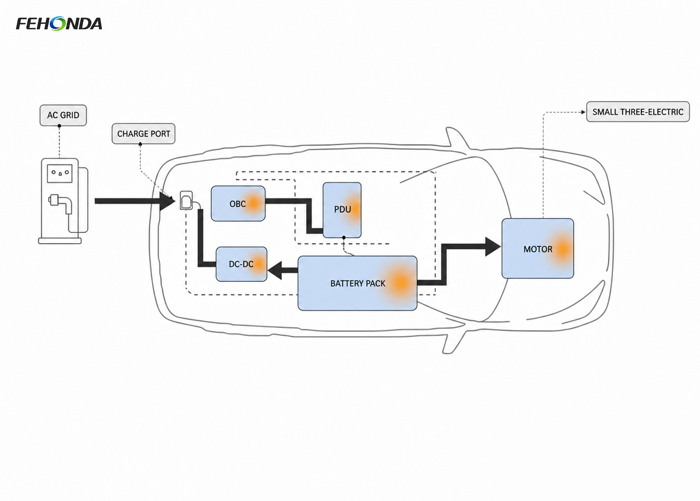
The full AC charging path is short: charge point → inlet → OBC → battery. Every watt lost becomes heat inside the charger, so thermal design and electrical topology are developed together—not sequentially.
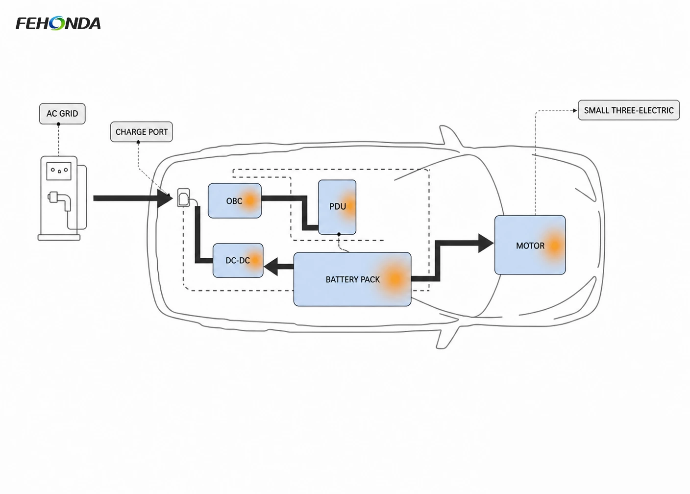
Figure 1. The OBC in the vehicle AC charging path, and its place inside the small three-electric group.
One practical constraint that shapes the thermal design: the OBC has no fixed home in the vehicle. Depending on the OEM architecture it may be integrated with the DC/DC and PDU into a single multi-in-one power unit, mounted under the rear seat, or placed in a front compartment. That decision sets the available airflow, the ambient temperature and the coolant loop — and therefore the material requirements.
2. Where the heat is generated inside an OBC
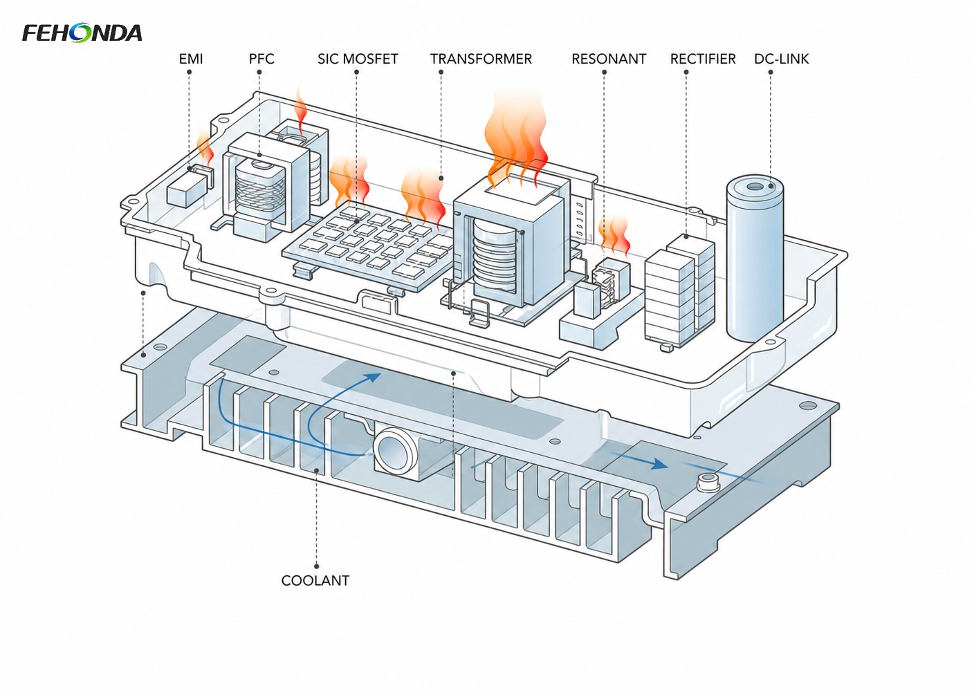
An OBC is not one hot component. It is a chain of stages, each with its own loss mechanism and its own temperature limit. Understanding the map is a prerequisite to choosing materials, because a single grade applied everywhere is almost always the wrong answer.
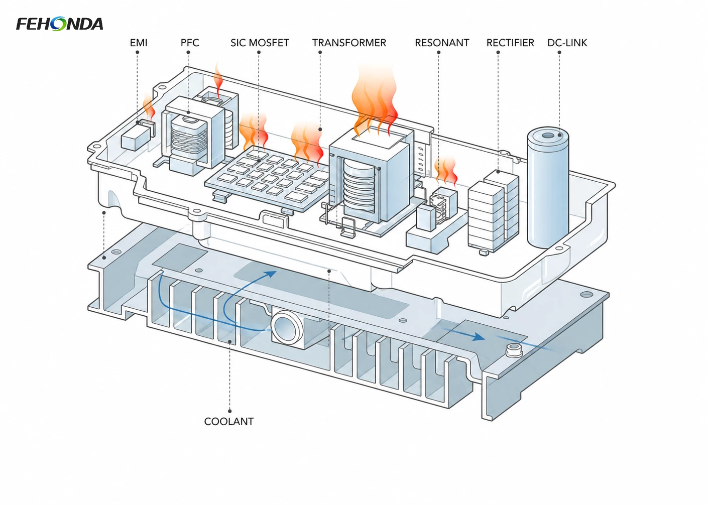
Figure 2. Internal OBC layout. The semiconductor stage and the magnetics are the two dominant heat sources.
4. Matching the material to the position
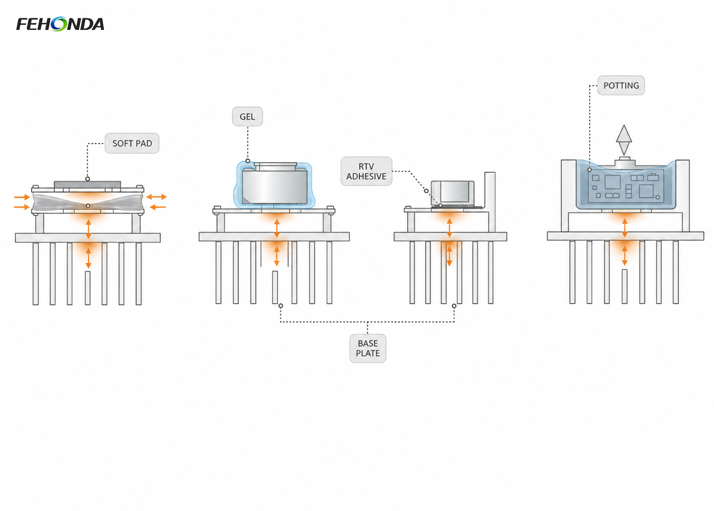
FEHONDA supplies a range of thermal materials for on-board chargers. The table below maps each family to the position it is intended for — the practical question is never "which material has the highest conductivity" but "which material survives this gap, this surface and this assembly process".
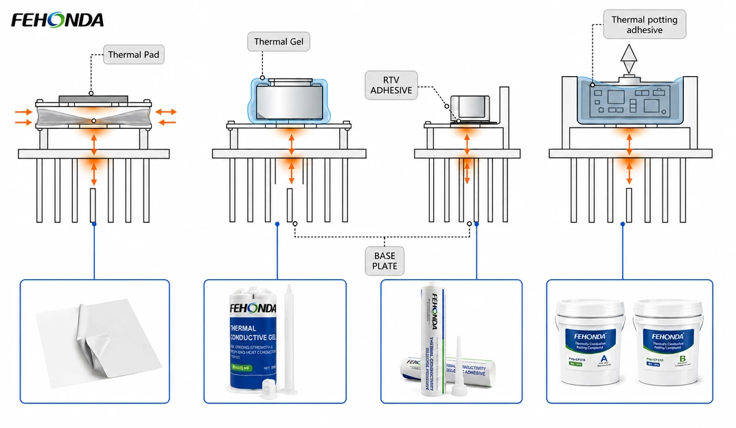
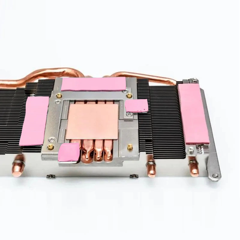
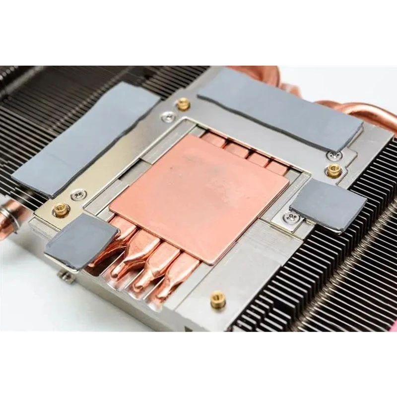
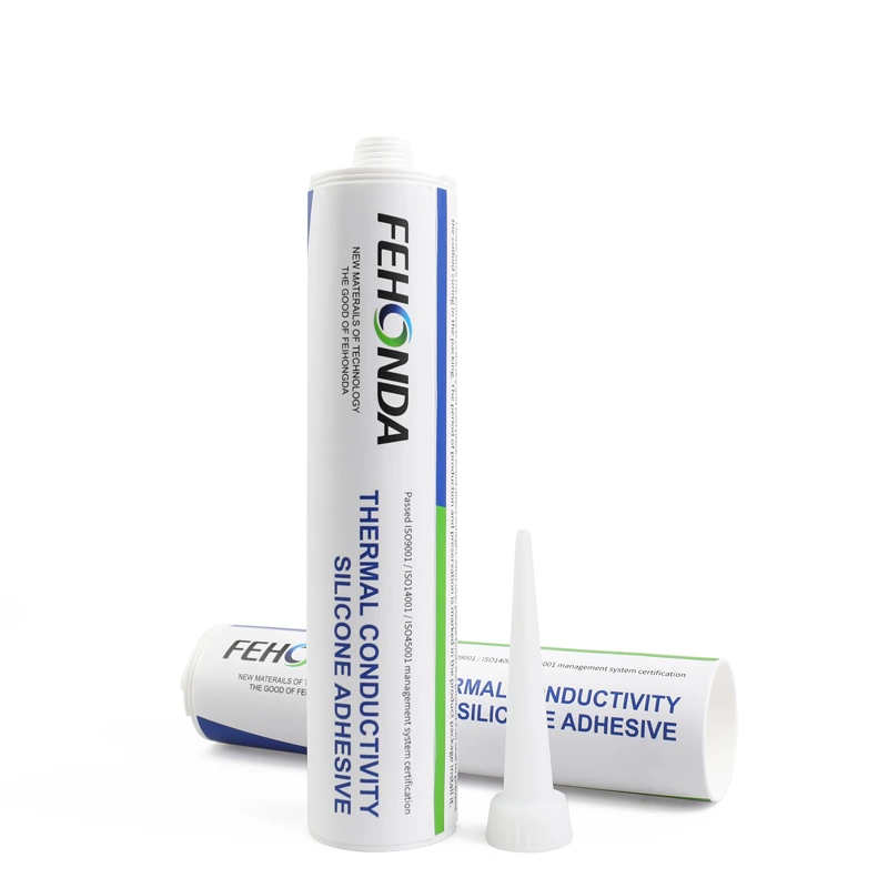
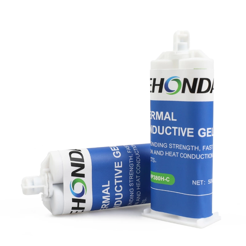
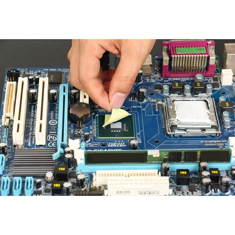
Figure 3. Four material forms in one assembly: soft pad, gel, RTV adhesive and potting compound.
| Location / Scenario |
Surface |
Recommended Material |
Recommended Thermal Conductivity |
Reason |
| Power Module → Cold Plate / Housing |
Flat, High Heat Flow |
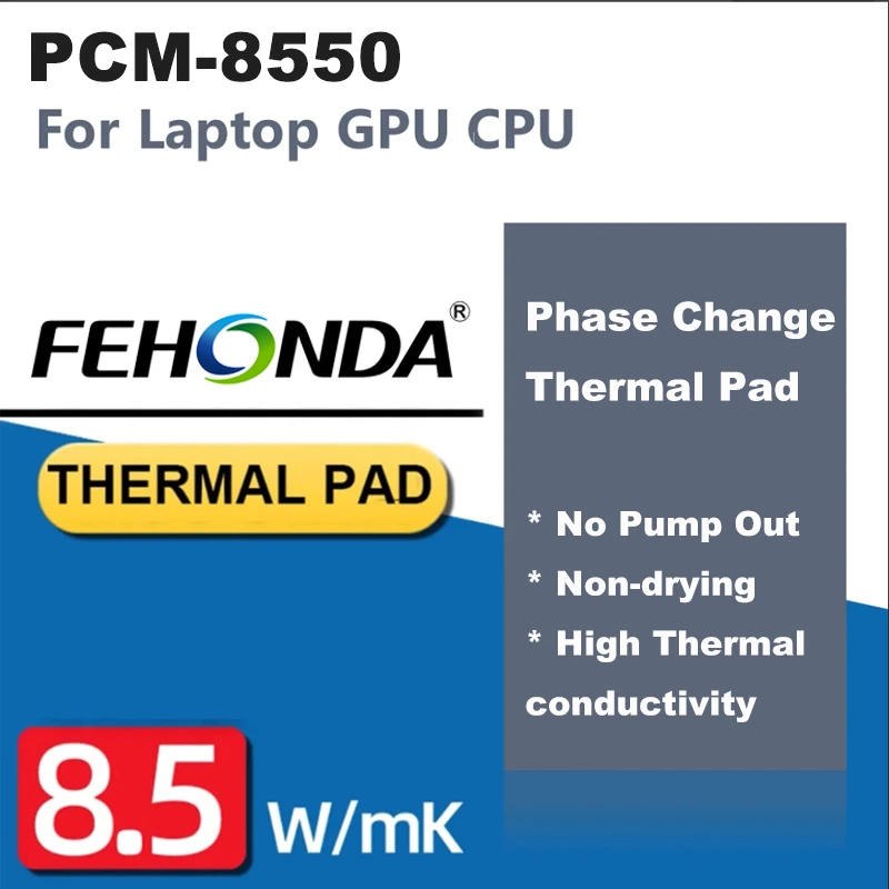
Ultra-soft Thermal Pad or Phase Change Material |
2.0–6.0 W/mK |
Mainstream OBC thermal interface range; low thermal resistance; ultra-soft pads facilitate rework |
| Transformer / Inductor |
Curved, Uneven |
Thermal Gel or Potting Compound |
1.5–4.0 W/mK |
Gel flows into windings, filling gaps that pads cannot conform to |
| Die-cast Aluminum Housing |
Rough, Uneven |
Self-adhesive Ultra-soft Silicone Pad |
2.0–6.0 W/mK |
Bonds under low pressure, avoiding PCB bending |
| High-voltage Connector (400V/800V) |
Requires Electrical Isolation |
Glass Fiber Reinforced Thermal Insulation Sheet |
1.1–3.5 W/mK |
Soft layer conformity + reinforcement layer provides dielectric strength (>6kV) |
| Control Board Protection |
PCBA Surface |
UV Conformal Coating |
— |
5-second curing; moisture-proof, mold-proof, anti-corrosion; suitable for mass production |
5. Feihongda Ultra-Soft Thermal Solutions: The Preferred Choice for OBC Interfaces
In OBCs, significant component height variations and poor housing flatness mean standard thermal pads require high compression force, easily causing PCB bowing and component damage. Feihongda's ultra-soft thermal pads (e.g., FHD-TS series) achieve excellent conformity at extremely low pressure, fundamentally solving this problem.
Height Compensation & Low Stress: Feihongda ultra-soft pads (Shore 00 30-70) bridge millimeter-level height differences, protect ceramic capacitors and solder joints, and enhance vibration resistance. The low-density F200D-B62 series is ideal for lightweight enclosures.
Irregular & Rough Surfaces: For curved surfaces like transformers and inductors, FHD-HP800H thermal gel is recommended. For uneven cast aluminum housings, self-adhesive ultra-soft silicone pads are the preferred choice.
High-Voltage Isolation: For 400V/800V systems, Feihongda offers high-insulation pads (breakdown >6kV) and glass-fiber reinforced thermal insulating pads, enabling composite protection: "soft layer for conformity + reinforced layer for dielectric strength."
Supplementary Solutions: Flat IGBT/SiC modules can be paired with Feihongda phase change materials, but ultra-soft pads are recommended for rework stations.
For material selection, request data from Feihongda on thermal conductivity, hardness, dielectric strength, and post-thermal-cycle thermal resistance to ensure the materials are production-ready and inspectable.
6. Protecting the control board: UV conformal coating
The control board inside an OBC faces years of heat, humidity, vibration, and chemical exposure — making protection as critical as thermal management.
Feihongda FHD-UV60 single-component UV-curable conformal coating is the ideal protective solution.
Curing in just 5 seconds under UV light, it perfectly fits high-volume production. Applied via brushing or spraying over PCB traces, solder joints, and components, it forms a thin dielectric film that delivers moisture-proof, anti-mold, and anti-corrosion protection.
Key parameters that meet stringent customer requirements:
- Flame Rating: V-0 (UL 94)
- Operating Temperature: -40~120℃
- Electrical Insulation: Surface Resistivity 10¹³ Ω, Dielectric Strength 30 KV/mm
- Physical Properties: Hardness 82 Shore D, Viscosity 250 cp
Feihongda FHD-UV60 provides excellent electromechanical stability, effectively extending the service life of OBC control boards.
7. Qualification: what automotive-grade actually means
A material that performs well on the bench can still fail in a vehicle. Automotive qualification exists to expose that gap, and the thermal material must be qualified as part of the assembly, not as a standalone coupon.
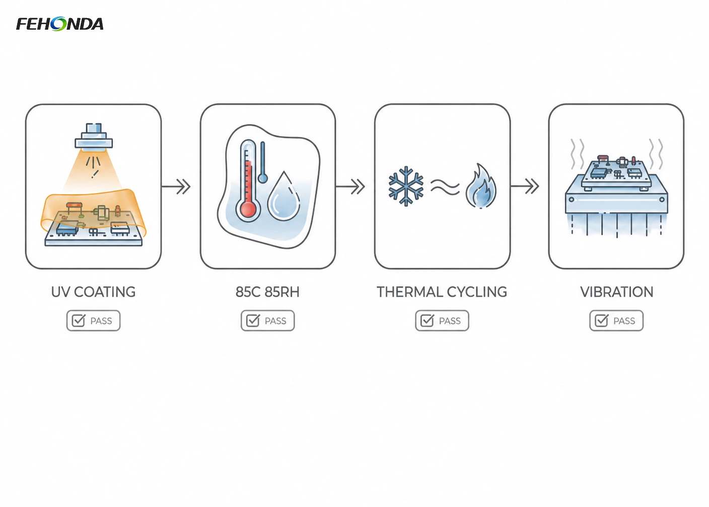
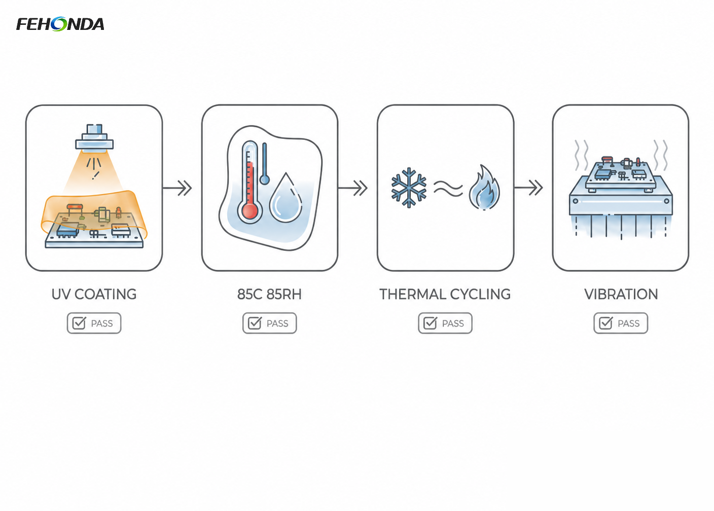
Figure 4. Four stresses that an OBC thermal material must survive: coating and cure, damp heat, thermal cycling, vibration.
- Thermal cycling. Typically –40 °C to +125 °C for 1,000 cycles or more, with electrical verification at the end. This is what exposes pump-out, delamination and loss of contact pressure.
- Damp heat. 85 °C at 85% relative humidity for 500 to 1,000 hours, confirming that neither the TIM nor the coating loses dielectric integrity.
- Thermal shock. Rapid transfer between –40 °C and +125 °C, which is the harshest test of adhesion to the housing wall.
- Vibration. Random vibration to an automotive profile with electrical monitoring, which is where unsupported heavy components and stiff, non-conforming pads fail first.
- Fluid and coolant compatibility. Where the OBC shares the vehicle coolant loop, the material must be verified against the specific coolant, not against a generic "coolant resistant" statement.
The governing reliability standards differ by component type — AEC-Q100 for integrated circuits, AEC-Q101 for discrete semiconductors, AEC-Q200 for passive components — and OEM specifications are normally derived from them. Thermal materials are not themselves covered by those documents, which is precisely why assembly-level testing is the right verification route.
8. A five-step selection checklist
1.Map heat sources. List every component above ~1 W dissipation, with loss estimate and temperature limit. This drives all downstream decisions.
2.Measure actual gaps. Include full tolerance stack-up (housing flatness, component height variation). This single step eliminates most wrong material choices.
3.Sort by surface type. Flat packages → pads or phase-change material. Curved/uneven surfaces (transformers, inductors, cast housings) → gel, ultra-soft pads, or potting.
4.Check electrical isolation separately. Where required, specify dielectric strength and consider a glass-fibre reinforced composite rather than relying on bulk material properties.
5.Confirm process before material. Cure time, dispensing rate, pot life, and reworkability often decide the final production choice — resolve these before tooling, not after.
9. Frequently asked questions
Why does an OBC need thermal interface materials?
Because the charger is sealed, compact and increasingly powerful. Even at 96% efficiency a 22 kW unit dissipates close to 900 W, and that heat must cross a solid interface to reach the housing or coolant. Without an interface material filling the microscopic air gaps, junction temperatures rise and the charger derates.
Which thermal material should go under an OBC power module?
A flat, high-flux package on a cold plate calls for the thinnest bond line you can hold in production — normally an ultra-soft thermal pad or a phase-change material. Choose by thermal resistance at the actual assembly pressure, not by conductivity alone.
What should I use on a transformer or resonant inductor?
A dispensable thermally conductive gel, or potting. These components present curved, uneven surfaces with variable gaps, which a flat pad cannot wet properly. Gel flows into the winding and removes the air that a pad would trap.
Do I need electrical isolation as well as heat transfer?
At 400 V and especially at 800 V, yes, at any interface to a grounded housing or cold plate. A composite TIM combining an ultra-soft pad with a glass-fibre reinforced insulating sheet gives low thermal resistance and specified dielectric strength in one part.
How is OBC thermal performance verified?
Thermal conductivity and impedance are measured by steady-state methods such as ASTM D5470, quoted with the test pressure and bond line thickness. Reliability is then verified at assembly level through thermal cycling, damp heat, thermal shock and vibration testing derived from the AEC standards.
10. Working with FEHONDA
FEHONDA supplies thermally conductive potting compounds, thermally conductive silica, thermally conductive gels, ultra-soft thermal pads and UV-curable conformal coatings for new energy vehicle power electronics, with conductivity grades spanning 1.5 to 6.0 W/(m·K) characterised under ASTM D5470.
Our sales and engineering support teams can help with grade selection, dispensing trials, coolant and fluid compatibility checks, coating qualification data against IPC-CC-830C, and product customisation. Send us your stack-up — power level, gap range at each position, mounting pressure, target junction temperature and service profile — and we will return a shortlist with sample recommendations.
📩 Contact our technical team: sales@fehonda.com