FEHONDA | Thermal Materials Technical Article
Why heat on a battery management board is a measurement problem, not just a reliability one — and which material belongs at each position
1. What the BMS does, and how it is built
BMS Core Functions
- Monitoring: Continuously measures cell voltage, pack current, and temperature to estimate state of charge (SOC) and state of health (SOH). Accuracy is the foundation for all protection and balancing decisions.
- Control: Manages charge/discharge, maintains thermal window, and limits current/voltage to prevent over-charge, over-discharge, and overload.
- Balancing: Equalizes series-connected cells via passive (resistive, generates heat on board) or active (energy transfer between cells) methods.
- Protection: Triggers safety actions (opens contactors, interrupts current, raises faults) when voltage, current, or temperature exceed limits. This is why BMS is a safety-critical function.
Architecture
- CMU (Cell Monitoring Unit): Sits near cells, performs analog measurement.
- BMU (Battery Management Unit): Aggregates data, computes, communicates.
- Distributed designs: Each module has a slave board — this is where thermal and material challenges concentrate.
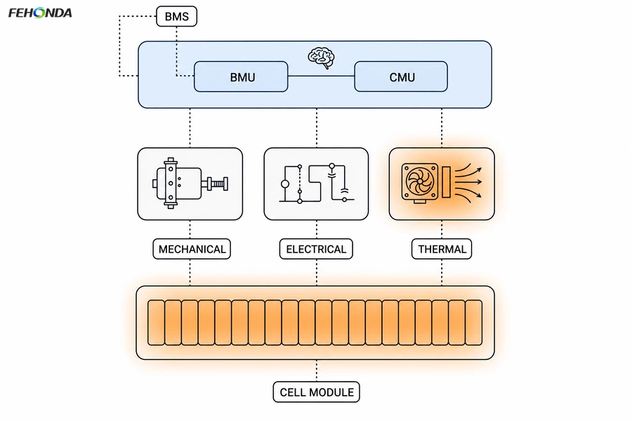
Figure 1. The five parts of a traction battery system, and where the BMS sits.
Thermal EMF & Measurement Drift
- Seebeck effect: A temperature difference across two joined metals generates a small voltage (thermal EMF). Though tiny, it directly impacts BMS accuracy since cell voltages are resolved at the millivolt level.
- Layout sensitivity: Even electrically symmetrical current-sense paths drift if their two halves sit in different thermal environments — e.g., a shunt resistor with a hot/cool end, a sense connector near balancing resistors, or uneven heat spreading in a copper pour. Any gradient creates an offset.
- Thermal design principle: BMS thermal management isn't just about staying below temperature limits; it's about minimizing gradients and giving heat a deliberate, symmetrical exit path away from measurement nodes.
- Leakage control: Humidity and contamination create surface leakage that also offsets measurements. Conformal coating (a standard BMS material) raises surface insulation resistance, suppressing these parasitic paths.
2. Where the heat is: a map of the BMS board
Before selecting a material, list the sources. A BMS board has five, and they differ enough that a single material applied everywhere is the wrong answer.
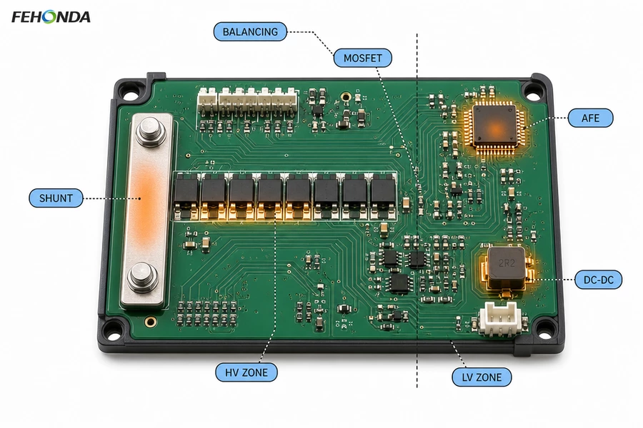
Figure 3. Heat sources on a BMS board, and the high-voltage / low-voltage boundary.
| Source |
Why it heats |
Typical magnitude |
Thermal consequence |
| Current shunt |
Pack current flowing through a low-value sense resistor; dissipation is I²R |
Small in absolute terms at typical values, but highly localised and continuous |
The most thermally sensitive location on the board, because it sits in the measurement path |
| Balancing resistors |
Passive balancing burns excess cell energy as heat |
Commonly tens to hundreds of milliwatts per channel, scaling with balancing current and channel count |
Distributed across the board; total dissipation is set by how many channels balance simultaneously |
| Protection MOSFETs |
Conduction and switching losses in the pack connection path |
Watts at high pack current |
Concentrated; needs a real copper path and often an interface to the housing |
| DC-DC supply |
Conversion losses feeding the board's own logic and isolation |
Sub-watt to a few watts |
Moderate and steady; often overlooked in thermal budgets |
| AFE and controller |
Quiescent power |
Low, typically well under a watt |
Low heat, but the highest sensitivity to temperature and to gradients |
Note the asymmetry in that table. The components producing the most heat — the shunt, the balancing bank, the MOSFETs — are not the components most sensitive to it. The sensitive part is the analogue front-end, which produces almost no heat of its own and suffers from everyone else's. Good BMS thermal design means moving heat out along a path that does not run across the measurement section, which normally means interfacing to the housing or a cold plate at the power end of the board.
Also note the boundary. A BMS board spans a high-voltage zone — cell taps, pack positive and negative — and a low-voltage logic zone, with isolation between them. Any thermal material crossing or approaching that boundary has to be assessed for dielectric strength and for creepage and clearance, not just for conductivity.
3. Thermal materials: which one goes where
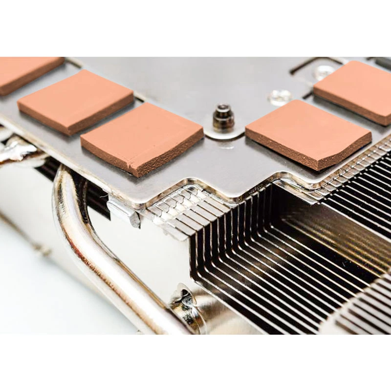
FEHONDA supplies thermally conductive silica, thermally conductive gel and thermally conductive pads for battery management boards, with conductivity grades spanning 1.5 to 6.0 W/(m·K). The table below maps each material form to the position it suits.
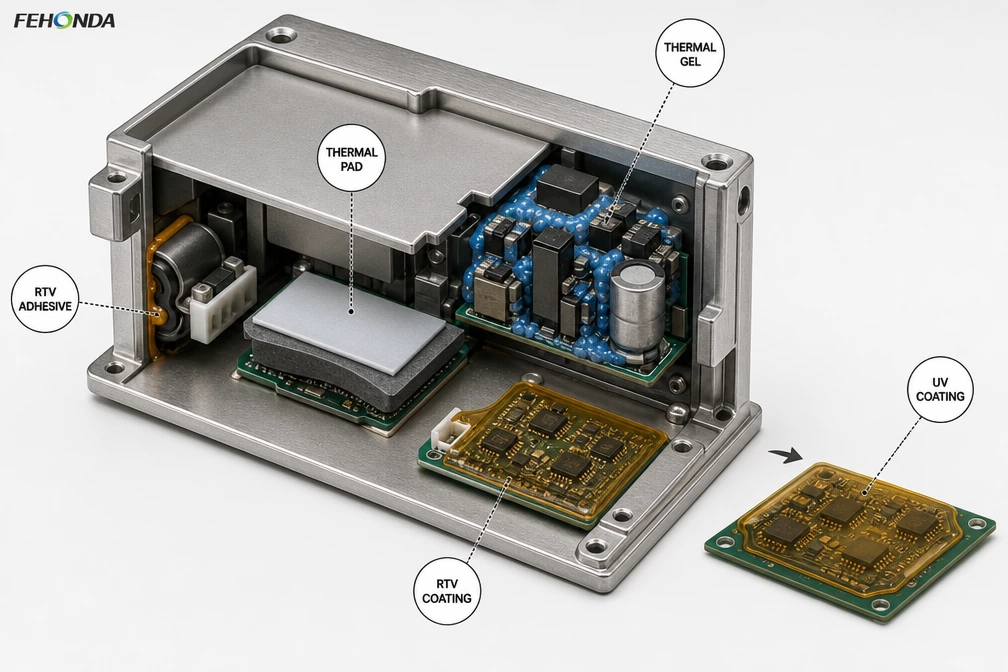
Figure 4. Five material applications on a BMS assembly, seen in cross-section.
| Material |
Position on the BMS |
Why it is chosen there |
Watch out for |
| Thermally conductive pad |
Under the shunt, under power MOSFETs, and between the board and the housing base or cold plate |
Flat, well-defined interfaces with a measurable gap; gives a repeatable bond line and, in isolating grades, a dielectric barrier in one part |
Compression force. A pad stiff enough to bridge a poorly controlled gap will load solder joints; match thickness to the real gap, not the nominal one |
| Thermally conductive gel |
Around balancing resistor banks, mixed-height component clusters, and anywhere the gap varies across the board |
Dispensable and conformable, so it flows around components of different heights and fills variable gaps without a fixed thickness; suited to automated dispensing |
Dispense volume control and, in uncured systems, long-term migration under vibration |
| RTV adhesive |
Bonding heavier components to the housing or base plate, and providing a heat path plus mechanical retention where a clamp is impractical |
Combines heat transfer with structural bonding and seals against moisture; removes the need for mechanical fixing in tight enclosures |
Cure time and fixture holding during cure; some chemistries release by-products during cure |
| Potting compound |
Whole-module encapsulation of a slave board or sensor assembly |
Fills every void, locks components against vibration, and provides a secondary heat path to the enclosure |
Reworkability, and the added mass in a pack where weight is contested |
The recurring principle is the same one that applies in chargers and inverters: conductivity sets the ceiling, but bond line thickness and wetting set the actual result. On a BMS board this is amplified, because the gaps are small, the components are mixed-height, and the board is often assembled into a housing that flexes.
One additional caution specific to this application. Because the shunt and the sense network are thermally sensitive, prefer a material and a placement that pulls heat downwards into the base plate or outwards to the housing, rather than one that spreads it laterally across the board. The objective is to remove heat from the board, not to distribute it more evenly across the measurement area.
4. Protecting the board: conformal coating
Thermal materials move heat. Conformal coating does a different job: it keeps moisture, contamination and condensation away from the board surface, which protects both reliability and measurement accuracy by suppressing leakage current.
The qualification standard for coating materials is IPC-CC-830, which sets the insulation resistance, thermal shock, humidity and flammability requirements that most automotive specifications are derived from. IPC-A-610 then defines what an acceptable coating job looks like — coverage, thickness and defects. The first tells you whether the material is any good; the second tells you whether the application is.
RTV or UV: how the two cure differently
Both are used on automotive boards, and the choice is mostly a process decision rather than a performance one.
| Consideration |
RTV (moisture-cure silicone) |
UV-curable coating |
| Cure mechanism |
Reacts with ambient humidity; cures through the film |
Cures in seconds under UV, with a secondary mechanism for shadowed areas |
| Cure speed |
Slow. Tack-free in minutes to hours; full properties and adhesion can take up to about 72 hours |
Very fast; suited to inline production and high throughput |
| Shadowed areas |
Cures without line of sight, so it reaches under components |
Needs a secondary moisture or thermal cure for areas the light does not reach |
| Adhesion development |
Adhesion lags behind cure, so handling too early can damage the film |
Handling strength develops almost immediately |
| Process fit |
Simple equipment; longer work-in-progress time |
Requires UV lamps and control of dose and geometry; much shorter cycle |
| Typical use |
Lower volume, thicker films, assemblies with heavy shadowing |
High-volume automotive production where tact time matters |
Whichever chemistry is chosen, four points decide whether it works in service:
- Keep it off anything that must make contact. A coating is a dielectric. Connector pins, test points, mating surfaces and grounding points must be masked, and this is the single most common coating specification error.
- Control the film thickness. Ranges are defined per material type in the standards, and a coating that is too thin stops protecting while one that is too thick can trap heat or crack under thermal cycling.
- Verify insulation resistance after humidity exposure, not just on a dry board. The failure mode the coating prevents — leakage current and electrochemical migration — only appears under moisture and bias.
- Check the flammability rating with its certified thickness. A rating achieved at one thickness does not automatically carry to another.
5. Automotive qualification: what the material has to survive
A BMS is a safety function, and the materials inside it are expected to survive the vehicle and to be documented.
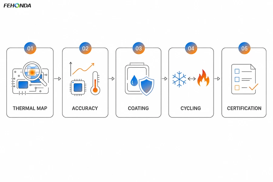
Figure 5. Five areas a BMS thermal and protective material specification has to cover.
| Requirement |
What it asks |
What to ask your supplier for |
| Component grade |
Automotive-qualified parts, typically rated –40 °C to +125 °C and qualified for long service life |
AEC-Q100 evidence for integrated circuits and AEC-Q200 for passive components, as applicable |
| Functional safety |
The BMS is developed to an ASIL level under ISO 26262, with defined fault detection and diagnostic coverage |
Any reliability data, FIT figures or FMEDA input the material supplier can support; treat vague “compliant” claims with caution |
| Environmental |
Thermal cycling, humidity, vibration, shock and salt spray per the applicable automotive environmental standard |
Cycling and damp-heat data on the material, and ideally on the potted or coated assembly |
| Isolation coordination |
Creepage and clearance defined for the working voltage, following the applicable insulation standard |
Dielectric strength and volume resistivity, plus comparative tracking index where relevant |
| Coating qualification |
Material qualified to IPC-CC-830, applied to an IPC-A-610 acceptable standard |
Test reports showing substance-level or property-level results, not a summary statement |
Two practices make this materially easier. First, qualify the assembly rather than the coupon — a material that passes as a standalone specimen can still fail as part of a board, because adhesion, cure and stress all depend on the substrate and the geometry. Second, ask for documentation at the start of a project rather than at the end; the compliance and reliability pack is far cheaper to assemble during selection than during a certification crunch.
6. A five-step selection checklist
- Map the heat and the measurement together. List every source above roughly half a watt, and mark which ones sit near the sense network. This is the step that distinguishes a BMS thermal design from a generic power board one.
- Measure the real gap at each position. Use the full tolerance stack-up, including board flatness, component height variation and housing flex. Thin, flat interfaces get pads; variable or mixed-height interfaces get gel.
- Decide the heat path deliberately. Heat should leave the board at the power end, into a base plate or housing, not spread laterally across the measurement section.
- Specify the electrical requirement separately. Where the material approaches the isolation boundary, state the working voltage and require dielectric strength, not just conductivity.
- Confirm the process before freezing the material. Dispensing, cure time, masking, handling strength and reworkability frequently decide the final choice in production, and they are cheaper to settle before tooling than after.
7. Working with FEHONDA
FEHONDA supplies thermally conductive potting adhesive, thermally conductive silica, thermally conductive gel, thermal pads, composite TIM constructions and conformal coatings for new energy vehicle battery systems, power electronics and control assemblies, with thermal conductivity grades spanning 1.5 to 6.0 W/(m·K).
For BMS programmes we support grade selection against your board layout, dispensing and cure trials, coating selection and masking review, compliance documentation, custom die-cutting and OEM packaging, and product customisation. Send us your board thermal map, the gap range at each position, your working voltage and isolation boundary, and your production volume, and we will come back with a shortlist, sample recommendations and lead time.
8. Frequently asked questions
Which thermal material should go under a BMS current shunt?
A thermally conductive pad on a flat, well-controlled interface, specified by thermal resistance at the actual assembly pressure rather than by conductivity alone. The shunt is both a heat source and a measurement node, so the heat path should take heat away from it rather than spread it across the board.
When should I use thermally conductive gel instead of a pad?
Where the gap varies or the surface is not flat — balancing resistor banks, mixed-height component clusters, or boards assembled into a housing with significant tolerance. Gel is dispensable and conforms without a fixed thickness, so it wets surfaces a pad would only touch at a few points.
Should a BMS board be conformal coated?
For an automotive application, generally yes. Coating raises surface insulation resistance, which suppresses the leakage and electrochemical migration that cause both field failures and measurement drift. Specify the material to IPC-CC-830 and the application to IPC-A-610, and mask every surface that must make electrical contact.
RTV or UV conformal coating — which is better?
Neither is universally better. UV cures in seconds and suits high-volume production, but needs a secondary cure for shadowed areas. RTV cures without line of sight and handles heavier shadowing, but full properties and adhesion can take up to about 72 hours. Choose on process and geometry rather than on performance alone.